Power control system for current regulated light sources

a power control system and current regulated technology, applied in the field of electrical and lighting, can solve the problems of large and relatively expensive electrolytic capacitors in conventional pfc controllers to accommodate voltage spikes, and the response of conventional switching power converters using compensators is generally slow

Active Publication Date: 2008-09-18
SIGNIFY HLDG BV
View PDF99 Cites 331 Cited by
  • Summary
  • Abstract
  • Description
  • Claims
  • Application Information

AI Technical Summary

Benefits of technology

[0031]In one embodiment of the present invention, a light emitting diode (LED) lighting system includes a power factor correction (PFC) and LED drive controller. The controller includes a digital signal processor, coupled to the LED feedback node and configured to: operate from a digital level supply voltage; generate a PFC control signal; and generate an LED current control signal. The controller further includes a first buffer, coupled to the processor, and configured to: operate from a medium level supply voltage. The medium level supply voltage is greater than the digital level supply voltage. The controller is further configured to receive the PFC control signal and convert the PFC control signal into a PFC switch control signal to control conductivity of a high voltage PFC switch. The controller further includes a second buffer, coupled to the processor, and configured to: operate from the medium level supply voltage; receive the LED current control signal; and convert the LED current control signal into an LED current control switch signal to control conductivity of a high voltage LED current control switch.
[0032]In another embodiment of the present invention, a method includes operating a digital signal processor of a power factor correction (PFC) and output voltage controller from a digital level supply voltage and generating a PFC control signal; and generating an LED current control signal. The method further includes operating a first buffer, coupled to the processor, from a medium level supply voltage. The medium level supply voltage is greater than the digital level supply voltage; receiving the PFC control signal. The method also includes converting the PFC control signal into a PFC switch control signal to control conductivity of a high voltage PFC switch and operating a second buffer, coupled to the processor, from the medium level supply voltage. The method further includes receiving the LED current control signal and converting the LED current control signal into an LED current control switch signal to control conductivity of a high voltage LED current control switch.
[0033]In a further embodiment of the present invention, a light emitting diode (LED) lighting system includes an LED lighting power system. During normal operation of the LED lighting system the LED lighting power system generates a first source voltage relative to a common voltage. The first source voltage is a link voltage. The LED lighting power system includes a switching power supply having a power factor correction (PFC) switch, wherein during normal operation of the LED lighting system, the PFC switch of the LED lighting power system operates at a current node voltage less than or equal to 0.1 times the first source voltage relative to the common voltage reference. The LED lighting power system also includes an LED current control switch, wherein during normal operation of the LED lighting system, the LED current control switch operates at a current node voltage less than or equal to 0.1 times the first source voltage relative to the common voltage reference. The LED lighting system further includes a PFC and output voltage controller coupled to conductivity control nodes of the first and LED drive current switches. During normal operation of the lighting control system, the controller operates from a second source voltage relative to the common voltage and controls conductivity of the PFC switch and the LED current control; and at least one LED coupled to the LED current control switch.

Problems solved by technology

Thus, increasing current supplied to an LED increases the brightness of the LED and decreasing current supplied to the LED dims the LED.
Conventional switching power converters using compensators generally respond relatively slowly to large changes in load power demand.
Additionally, conventional PFC controllers often include large and relatively expensive electrolytic capacitors to accommodate voltage spikes.

Method used


Image

  • Power control system for current regulated light sources
  • Power control system for current regulated light sources
  • Power control system for current regulated light sources

Examples


Embodiment Construction

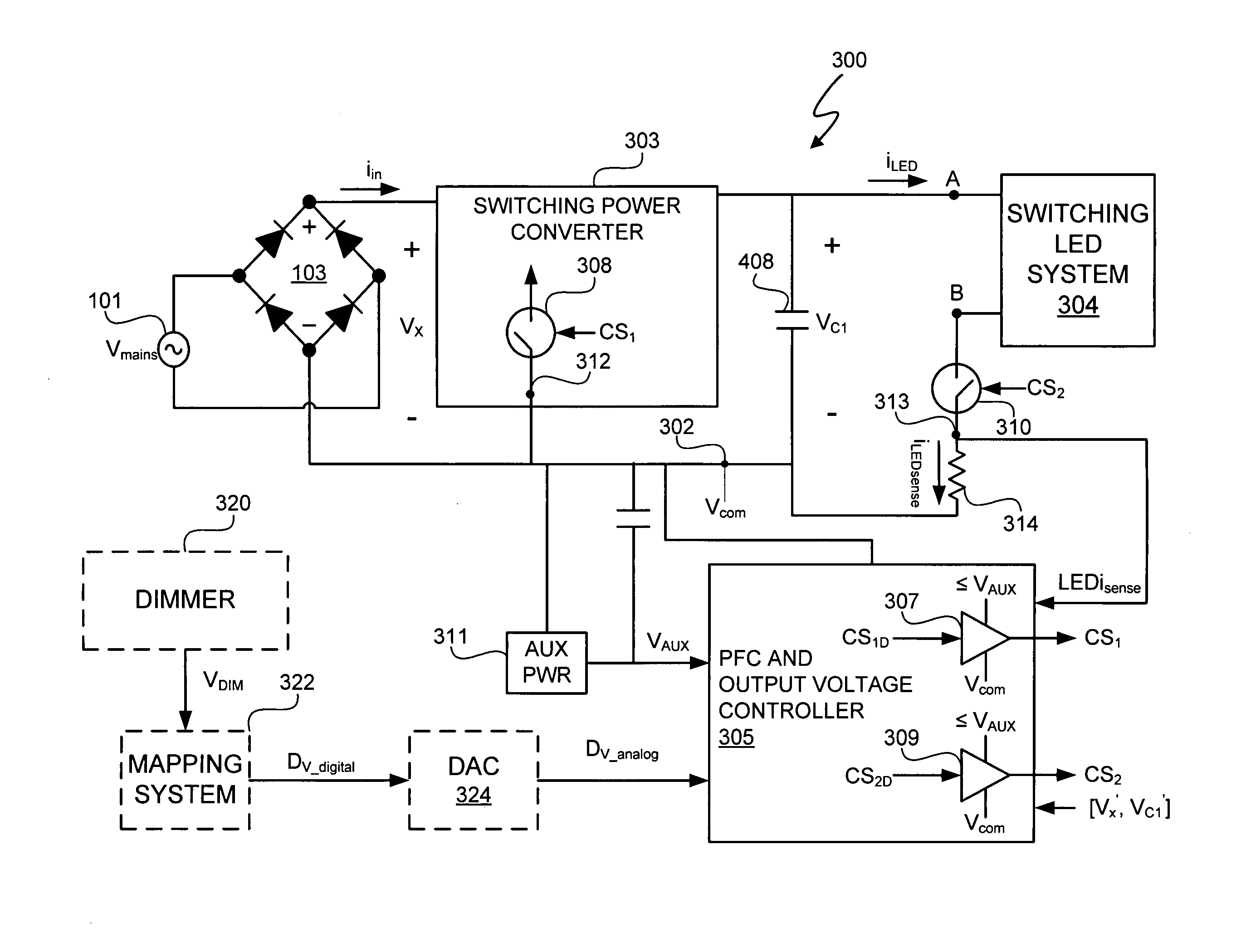
[0050]A light emitting diode (LED) lighting system includes a PFC and output voltage controller and a LED lighting power system. The LED lighting power system operates from a primary supply voltage derived from a primary power supply. The controller operates from an auxiliary power source supply, which provides an auxiliary voltage less than a link voltage generated by the LED lighting power system relative to a common reference voltage at a common reference node. By utilizing a lower voltage, in at least one embodiment, the controller can be manufactured at a lower cost than a comparable controller supplied by the primary power supply utilized by the LED lighting power system. Additionally, during normal operation of the LED lighting system, a power factor correction (PFC) switch and an LED drive current switch of the LED lighting system, that respectively control power factor correction and LED drive current, are coupled to the common reference node and have control node-to-common...


PUM


Abstract

A light emitting diode (LED) lighting system includes a PFC and output voltage controller and a LED lighting power system. The controller advantageously operates from an auxiliary voltage less than a link voltage generated by the LED lighting power system. The common reference voltage allows all the components of lighting system to work together. A power factor correction switch and an LED drive current switch are coupled to the common reference node and have control node-to-common node, absolute voltage that allows the controller to control the conductivity of the switches. The LED lighting system can utilize feed forward control to concurrently modify power demand by the LED lighting power system and power demand of one or more LEDs. The LED lighting system can utilize a common current sense device to provide a common feedback signal to the controller representing current in at least two of the LEDs.

Description

CROSS REFERENCE TO RELATED APPLICATIONS[0001]This application claims the benefit under 35 U.S.C. § 119(e) and 37 C.F.R. § 1.78 of U.S. Provisional Application No. 60 / 894,295, filed Mar. 12, 2007 and entitled “Lighting Fixture.” U.S. Provisional Application No. 60 / 894,295 includes exemplary systems and methods and is incorporated by reference in its entirety.[0002]U.S. Provisional Application No. 60 / 909,458, entitled “Ballast for Light Emitting Diode Light Sources,” inventor John L. Melanson, Attorney Docket No. 1666-CA-PROV, and filed on Apr. 1, 2007 describes exemplary methods and systems and is incorporated by reference in its entirety.[0003]U.S. patent application Ser. No. ______ entitled “Ballast for Light Emitting Diode Light Sources,” inventor John L. Melanson, Attorney Docket No. 1666-CA, and filed on Mar. 12, 2008 describes exemplary methods and systems and is incorporated by reference in its entirety.[0004]U.S. patent application Ser. No. 11 / 926,864, entitled “Color Variati...

Claims


Application Information

Patent Timeline
Patent Type & Authority Applications(United States)
IPC IPC(8): H05B39/04H05B37/02G05F1/00H05B44/00
CPCH05B33/0815Y10S315/04Y02B20/347H05B33/0818H05B45/38H05B45/355Y02B20/30
Inventor MELANSON, JOHN L.
Owner SIGNIFY HLDG BV
Why Eureka
Try Eureka