Power control system for reducing power to lighting systems

a technology of power control system and lighting system, which is applied in the direction of electric variable regulation, process and machine control, instruments, etc., can solve the problems of insufficient power available on certain electrical power grid networks to supply system loads, insufficient power consumption of fluorescent lighting system, contacts wear out and burn up beyond use, etc., to achieve the effect of reducing transient currents

Inactive Publication Date: 2005-06-14
ASP CORP
View PDF11 Cites 67 Cited by
  • Summary
  • Abstract
  • Description
  • Claims
  • Application Information

AI Technical Summary

Benefits of technology

[0012]The above objectives are accomplished according to the present invention by providing a power control system for controlling the power supplied to a lighting system and limiting power during time of peak demands and the like wherein the lighting system includes a power source and a lighting load connected to the power source. The control system comprises a main transformer having a first winding and a second winding, the first winding being connected between the power source and the lighting load. A solid-state switching circuit is connected between the power source and the second winding of the main transformer which includes a toroidal transformer connected to the power source having a plurality of electrical transformer taps having prescribed voltage values. A plurality of solid-state tap switches are connected to the transformer taps and to the second winding of the main transformer to apply one of the prescribed voltage values across the main transformer. A system controller having an input for receiving a change voltage signal representing a selected load voltage to be applied to the lighting load, is connected to the tap switches for selectively closing one of the tap switches to produce the prescribed voltage value across the second winding of the main transformer. In this manner, the selected load voltage is output across the first winding of the main transformer and applied to the lighting load without interruption of the lighting. In an advantageous aspect of the invention, a transient control circuit is connected across an output of the tap switches for dissipating transient currents and voltages during changing of the tap switches. The transient control circuit comprises a solid-state control switch and a resistor connected in series across the second winding of the main transformer. The transient control circuit includes a second solid-state control switch connected in series with the second winding of the main transformer and neutral to disconnect the main transformer under the control of a soft-start circuit.
[0013]The control sequences the switching of the tap switches and the transient control and soft-start circuits and to reduce transient currents during change of the tap switches in response to the controller receiving an input signal to change power to the lighting load. The controller may be programmed to include tap switch switching instructions for switching from a currently closed tap switch to a newly selected tap switch in response to the input signal. The programmed instructions include a routine of (1) control switch instructions for closing the first control switch upon receipt of a voltage change signal so that the resistor is placed across the second winding; (2) control switch instructions for opening the second control switch to disconnect the second coil of the main transformer from the power source after soft-starting conditions are satisfied; (3) tap switch instructions for opening the currently closed tap switch and closing the selected tap switch; and (4) control switch closing instructions closing the second control switch and opening instructions for opening the first control switch after the tap switches have been changed.
[0014]The system includes a visual display, and the computer program includes a routine for displaying the status of the power control system on the visual display. The programmed controller includes instructions for alerting an external device if the power control system has been in a high voltage mode for a prescribed period of time. The programmed controller also includes instructions for setting the power control system in the high voltage mode in the event load voltage drops below a prescribed low voltage for a prescribed period of time.

Problems solved by technology

In previous years, there have been periods of time in which the power available on certain electrical power grid networks is insufficient to supply the loads on the system.
In particular, large grocery stores and retail complexes have been required to lower the power consumption of fluorescent lighting systems during the peak demand hours.
Because there is a certain amount of energy in a transformer, current spikes occur during switching using mechanical contacts so that the contacts wear out and burn up beyond use.
Therefore, the use of manual switching or mechanical contact relay switching in transformer systems has been an obstacle to the use of these systems.
While a number of solutions have been provided to the problems encountered in power reduction systems caused by autotransformers and mechanical switching, considerable attention still needs to be given to the problems.
In particular, the provision of the power reduction systems for lighting and the like wherein the power reduction system can be incorporated with other sophisticated electronics such as those found in environmental control panels is a problem to which considerable attention need be given.

Method used


Image

  • Power control system for reducing power to lighting systems
  • Power control system for reducing power to lighting systems
  • Power control system for reducing power to lighting systems

Examples


Embodiment Construction

[0023]Referring now to the drawings, the invention will now be described in more detail.

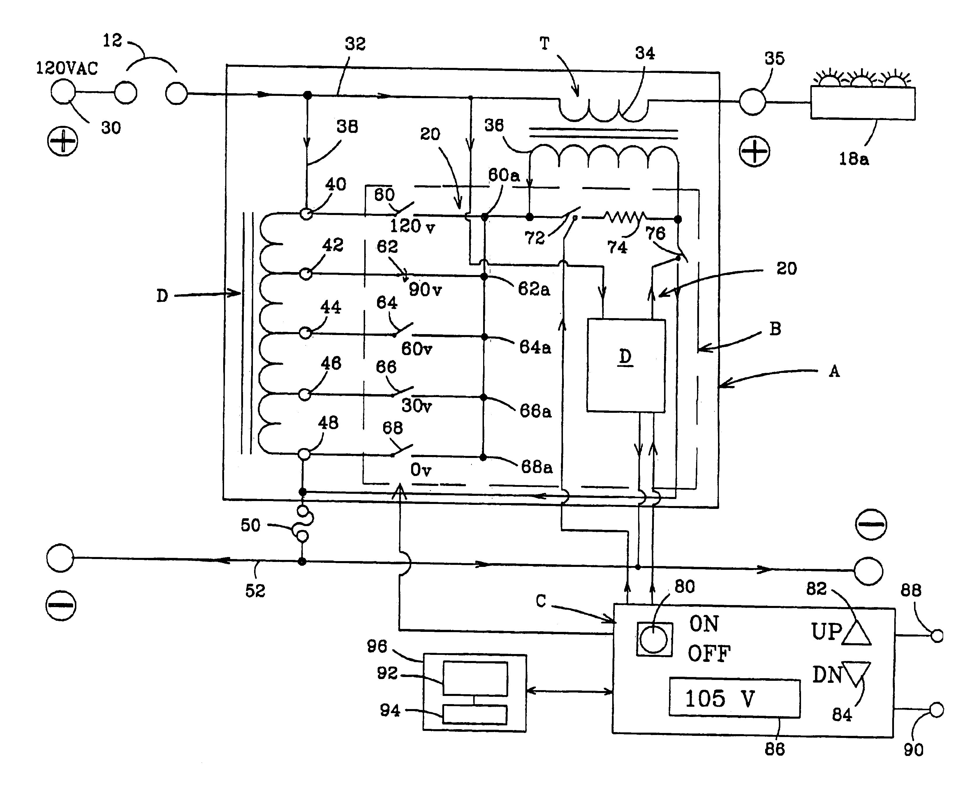
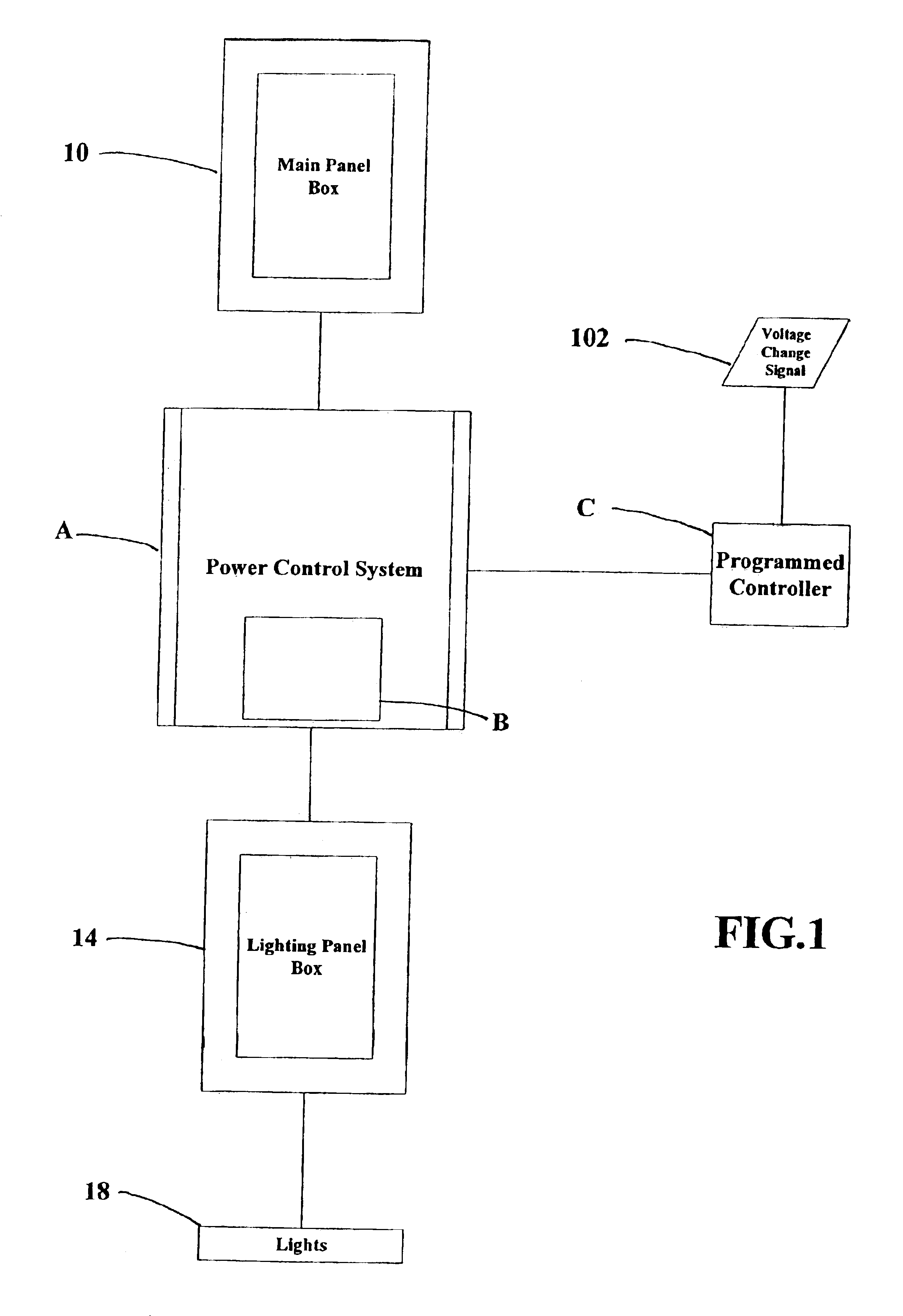
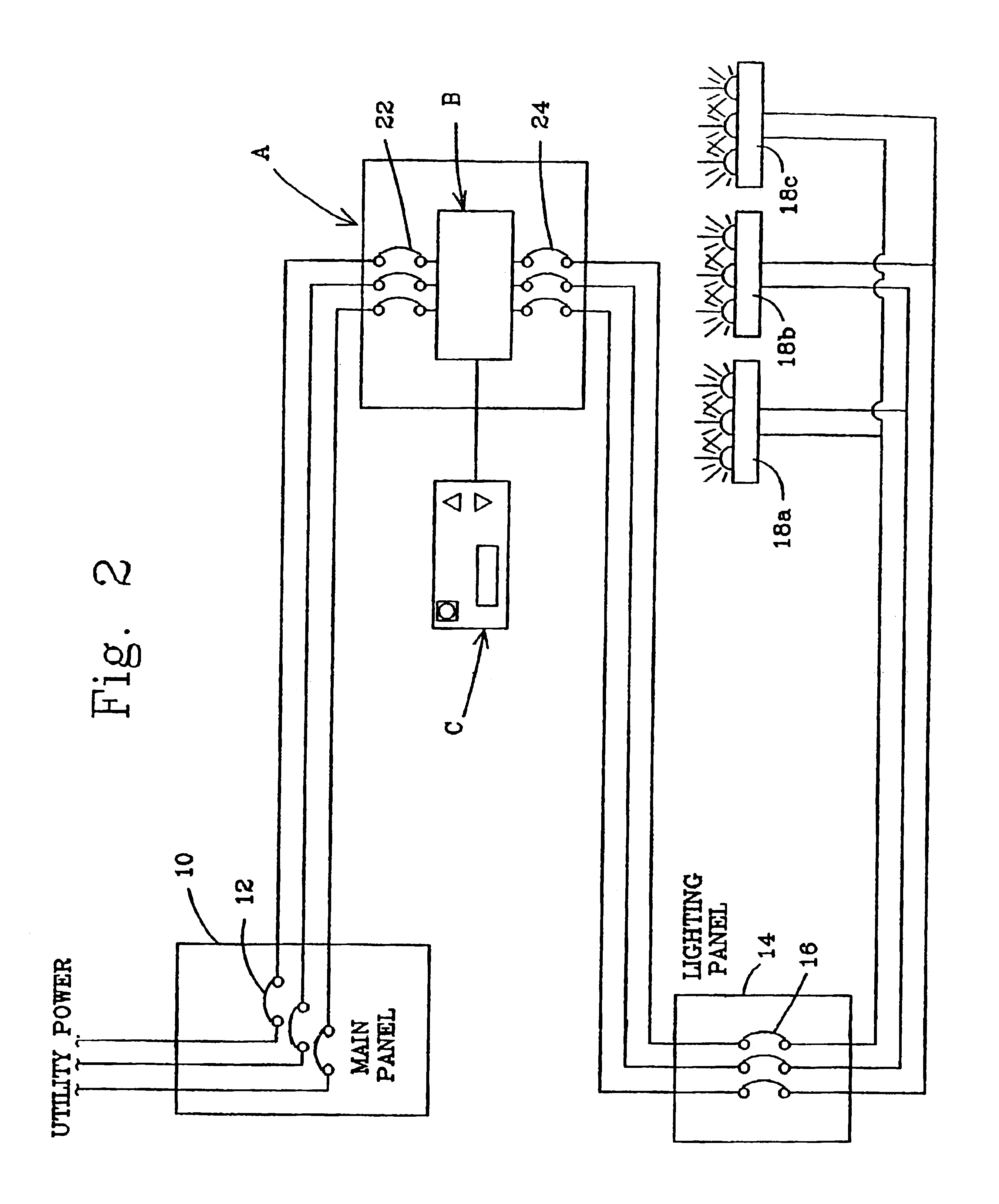
[0024]Referring to FIGS. 1 and 2, a power control system, designated generally as A, is illustrated for controlling the power delivered from a main electrical panel 10 to a lighting system 18 via electrical lighting panel 14 used in industrial and commercial buildings, such as grocery stores, large retail stores, warehouses, and the like. A main power, such as utility power, is delivered to main distribution panel 10 through a series of circuit breakers 12 and delivered to a lighting distribution panel 14 (FIG. 2). The lighting panel is also provided with a series of circuit breakers 16 that deliver power to banks of lighting fixtures, such as 18a, 18b, and 18c.

[0025]In accordance with the present invention, power control system A includes a solid-state switching circuit B connected between the main distribution panel 12 and lighting distribution panel 14. There is a main system transformer, des...


PUM


Abstract

A power control system is disclosed for controlling the power supplied to a lighting system and limiting power during time of peak demands and the like wherein the lighting system includes a power source and a lighting load connected to the power source. The control system comprises a main transformer having a first winding and a second winding, the first winding being connected between the power source and the lighting load. An autotransformer connected to the power source having a plurality of electrical transformer taps with prescribed voltage values. A plurality of solid-state tap switches is connected to the transformer taps and to the second winding of the main transformer to apply the prescribed voltage values across the second winding. A system controller has an input for receiving a voltage change signal representing a selected load voltage to be applied to the lighting load. The controller is connected to the tap switches for selectively closing one of the tap switches to produce said prescribed voltage value across the second winding of the main transformer whereby the selected load voltage is output across the first winding of the main transformer and applied to the lighting load without interruption of the lighting. A transient control circuit is connected across an output of the tap switches for dissipating transient currents during switching of tap switches.

Description

BACKGROUND OF THE INVENTION[0001]This invention relates to a system for controlling the power delivered to HID and fluorescent light systems and, more particularly, to reducing the voltage to the lighting systems during periods of peak demand in the electrical power network and other prescribed periods of time to maximize efficiency and meet the guidelines imposed by regulatory parties.[0002]In previous years, there have been periods of time in which the power available on certain electrical power grid networks is insufficient to supply the loads on the system. This is particularly true during the summer months when increased demands are made on electrical power systems by air conditioning and the like. In order to alleviate this problem, power companies have been required to mandate power limits on commercial and industrial customers. In particular, large grocery stores and retail complexes have been required to lower the power consumption of fluorescent lighting systems during the...

Claims


Application Information

Patent Timeline
Patent Type & Authority Patents(United States)
IPC IPC(8): H05B41/38H05B41/40
CPCH05B41/40
Inventor BEATENBOUGH, BRYANHALEY, RYAN
Owner ASP CORP
Why Eureka
Try Eureka