Power converter

a power converter and converter technology, applied in the field of electric power converters, can solve the problems of power conversion efficiency drop, circuit hinders circuit configuration simplification, and power conversion efficiency decrease, so as to improve power conversion efficiency, simplify circuit configuration, and control efficient

Inactive Publication Date: 2007-04-05
SANKEN ELECTRIC CO LTD
View PDF2 Cites 15 Cited by
  • Summary
  • Abstract
  • Description
  • Claims
  • Application Information

AI Technical Summary

Benefits of technology

[0012] The power converter can directly induce AC voltage on secondary winding (9b, 9c) of transformer (9) by turning each switching element (4, 5, 4a, 5a) in oscillator (2) on and off advantageously without any inverter circuit or DC-AC converter to be connected to secondary winding (9b, 9c) of transformer (9) for simplification of circuit configuration. Also, polarity detector (51) detects polarity of AC voltage produced on secondary winding (9b, 9c) of transformer (9) to turn first and second regulatory switching elements (10, 35, 11, 36) on and off through drive circuit (25, 24, 50, 49) by detection signals output from polarity detector (51) so that this operation can attain an efficient control of AC power supplied to load (15, 40) from secondary winding (9b, 9c) for improvement in power conversion efficiency.
[0013] The power converter according to the present invention can materialize simplification of circuit configuration to provide an inexpensive power converter without an inverter circuit to be connected to secondary winding of transformer in a switching power generator. In addition, the power converter can efficiently control AC power supplied from secondary winding to load with simplified circuit configuration by turning first and second regulatory switching elements on and off in synchronization with AC voltage appearing on secondary winding of transformer to thereby accomplish a highly efficient power converter.

Problems solved by technology

In this way, the converter requires the double stages of high frequency switching operation inconveniently with associated increased switching noise and power loss by heat generated from positive and negative commutating diodes 26, 28 connected at the output stage of the switching power generator, thereby causing power conversion efficiency to drop.
The power amplifier shown in the above Japanese Disclosure turns the switches on and off by means of pulse signals for pulse number modulation of pulsatile AC voltage beneficially without smoothing capacitor, however, it requires a half-wave rectifier which undesirably causes decrease in power conversion efficiency like the converter shown in FIG. 10.
Moreover, the power amplifier needs a filtering circuit of a choke coil and a capacitor between output side of the switches and a load such as a speaker for demodulation into audio signals so that such a filtering circuit hinders simplification of circuit configuration.

Method used


Image

  • Power converter
  • Power converter
  • Power converter

Examples


Embodiment Construction

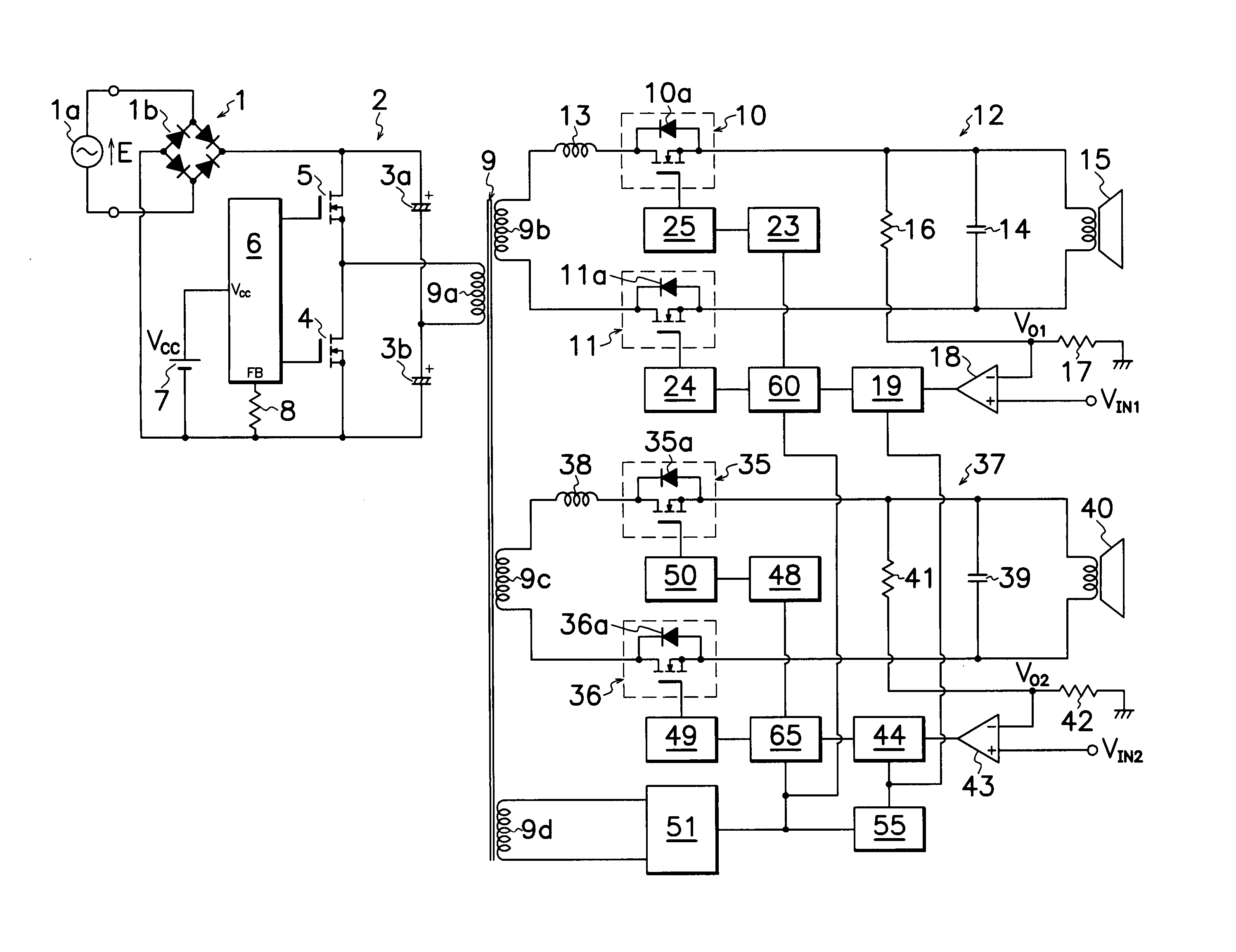
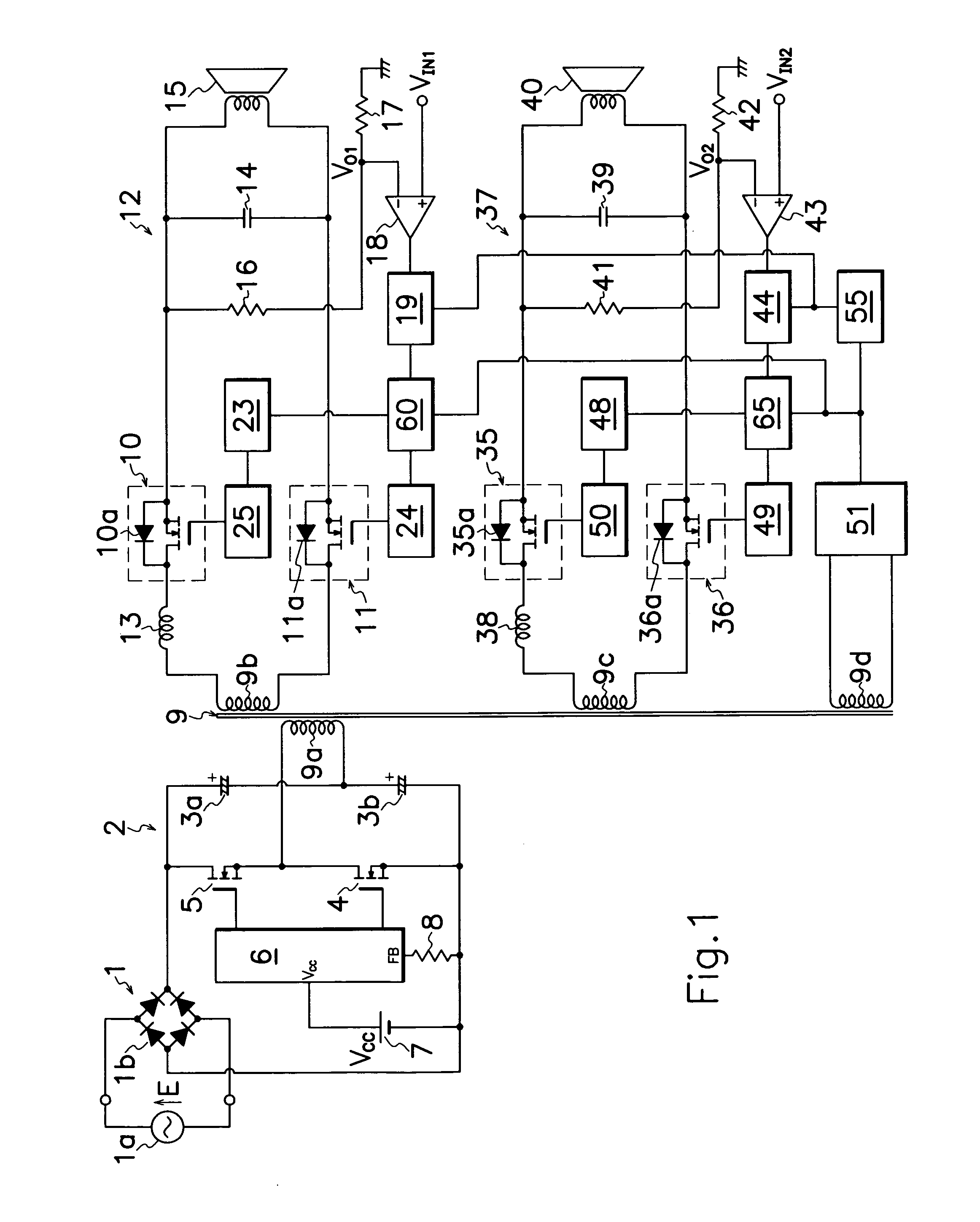
[0025] Embodiments of the power converter according to the present invention will be described hereinafter in connection with FIGS. 1 to 9 of the drawings. Same reference symbols as those shown in FIG. 10 are applied to similar portions in these drawings, omitting explanation therefor.

[0026] As shown in FIG. 1, the power converter of a first embodiment according to the present invention, has a switching power generator which comprises first and second main MOS-FETs 4 and 5 as two main switching elements connected in series to a DC power source 1 having a rectifying bridge circuit 1b connected to a commercial AC power source 1a; an oscillator 2 having two capacitors 3a and 3b connected in parallel to first and second main MOS-FETs 4 and 5 and in series to DC power source 1; a primary winding 9a of a transformer 9 connected between a junction of first and second main MOS-FETs 4 and 5 and a junction of two capacitors 3a and 3b; a main control circuit 6 for producing drive pulse signal...


PUM


Abstract

A power converter is provided which comprises two main MOS-FETs 4, 5 connected in series to a DC power source 1; an oscillator 2 which has two capacitors 3a, 3b connected in parallel to main MOS-FETs 4, 5; a primary winding 9a of a transformer 9 connected between a junction of two main MOS-FETs 4, 5 and a junction of two capacitors 3a, 3b; an electricity controller 12, 37 which comprises first and second regulatory MOS-FETs 10, 35, 12, 37 connected between respectively one and the other ends of a secondary winding 9b, 9c of transformer 9 and a speaker 15, 40; a polarity detector 51 for detecting the polarity of AC voltage produced on secondary winding 9b, 9c of transformer 9 by the on and off operation of MOS-FETs 4, 5 to generate detection signals; and a drive circuit 24, 25, 49, 50 for receiving detection signals from polarity detector 51 to control the on and off operation of first and second regulatory MOS-FETs 10, 35, 11, 36 to simplify the circuit configuration and improve power conversion efficiency in the power converter.

Description

TECHNICAL FIELD [0001] This invention relates to an electric power converter such as a power amplifier in particular of the type for activating an electric load such as a speaker for acoustic equipment. BACKGROUND OF THE INVENTION [0002] In acoustic equipment having a speaker as a load, recently, a D-class or digital amplifier has been in practical use to amplify audio signals recorded on optical diskettes such as CDs or compact disks, and an electric power converter has been utilized which comprises a switching power generator for supplying electric power from AC power source to D-class amplifier. Such a power converter incorporated with D-class amplifier and switching power generator is superior in power conversion efficiency to produce larger power signals in small size of the converter, compared to prior art power converter incorporated with low frequency transformer and analog amplifier. [0003]FIG. 10 shows an example of prior art power converters utilizing a switching power ge...

Claims


Application Information

Patent Timeline
Patent Type & Authority Applications(United States)
IPC IPC(8): H02M3/335
CPCH02M3/33561H02M3/33592H02M3/3376Y02B70/1475Y02B70/10
Inventor SHIGA, TOSHITAKAFURUKOSHI, RYUICHI
Owner SANKEN ELECTRIC CO LTD
Why Eureka
Try Eureka