Image forming apparatus and impact position displacement correction method

a technology of image forming apparatus and displacement correction method, which is applied in the direction of printing mechanism, spacing mechanism, printing, etc., can solve the problems of large misalignment, use of expensive detection units, and difficulty in accurately reading test patterns, so as to accurately correct the displacement accurate detection of the impact position of the liquid droplet, and simple configuration

Inactive Publication Date: 2008-09-18
RICOH KK
View PDF13 Cites 34 Cited by
  • Summary
  • Abstract
  • Description
  • Claims
  • Application Information

AI Technical Summary

Benefits of technology

[0017]In view of the foregoing, the present invention aims to accurately detect an adjustment pattern, which is formed of liquid droplets, for impact position displacement correction, and to accurately perform impact position detection and impact position displacement correction.
[0020]According to the above-described image forming apparatus and impact position correcting method, it is possible to accurately detect the impact position of a liquid droplet with a simple configuration and accurately correct displacement of the impact position of a liquid droplet to be ejected. Furthermore, because the reading unit is disposed on the carriage and is arranged close to a guide member that guides movement of the carriage, it is possible to reduce an adverse effect due to a displacement of the moving carriage, resulting in increased detection accuracy.

Problems solved by technology

A problem with such a liquid ejection type image forming apparatus, especially one that reciprocates a carriage with a recording head for ejecting liquid droplets to print images in opposite printing directions, i.e., in the forward path and the backward path, when the apparatus draws images such as a ruled line, a ruled line drawn by the head moving in one direction is often misaligned with a line drawn by the head moving in the opposite direction.
However, a wrong interpretation of the test result and an input error by a user unfamiliar with the apparatus might result in a greater misalignment.
In the case of forming a test pattern on a transport belt and detecting the color of the test pattern or reading the test pattern as in Patent Documents 1-3, some combination of the color of the transport belt and the color of the ink has a small difference in color, which makes it difficult to accurately read the test pattern.
In this case, for accurate color detection, it is necessary to use an expensive detecting unit including, e.g., a light source that emits lights of different colors and wavelengths.
For example, in the case where an electrostatic transport belt is used that includes an insulation layer forming the front surface and an intermediate resistance layer forming the back surface and containing carbon for providing conductivity, because the external color of the electrostatic belt is black, it is difficult to detect black ink when detecting a test pattern based only on reflectance or the image read by an imaging unit, thereby failing to provide accurate detection.
An increased number of filters and sensors result in a higher cost.
Increasing the detection accuracy limits the number of combinations of the inks to be used and the transport member.
If a laser beam is used which scans a very small point, small bits of foreign matter and scratches of the transport member easily affect the detection result, resulting in reduced detection accuracy.
The RGB sensor needs to have sensors one for each color, which means an increased cost.
This results in an increase of the cost.
If this system is used in a liquid ejection type image forming apparatus, detected droplets only have a small level difference from noise, which prevents highly accurate detection of a test pattern.
In the case where an optical sensor reads a test pattern formed on plain paper as a recording medium into which ink can penetrate, the test pattern blurs due to penetration of ink, which prevents accurate detection of the impact positions of ink droplets.

Method used


Image

  • Image forming apparatus and impact position displacement correction method
  • Image forming apparatus and impact position displacement correction method
  • Image forming apparatus and impact position displacement correction method

Examples


Embodiment Construction

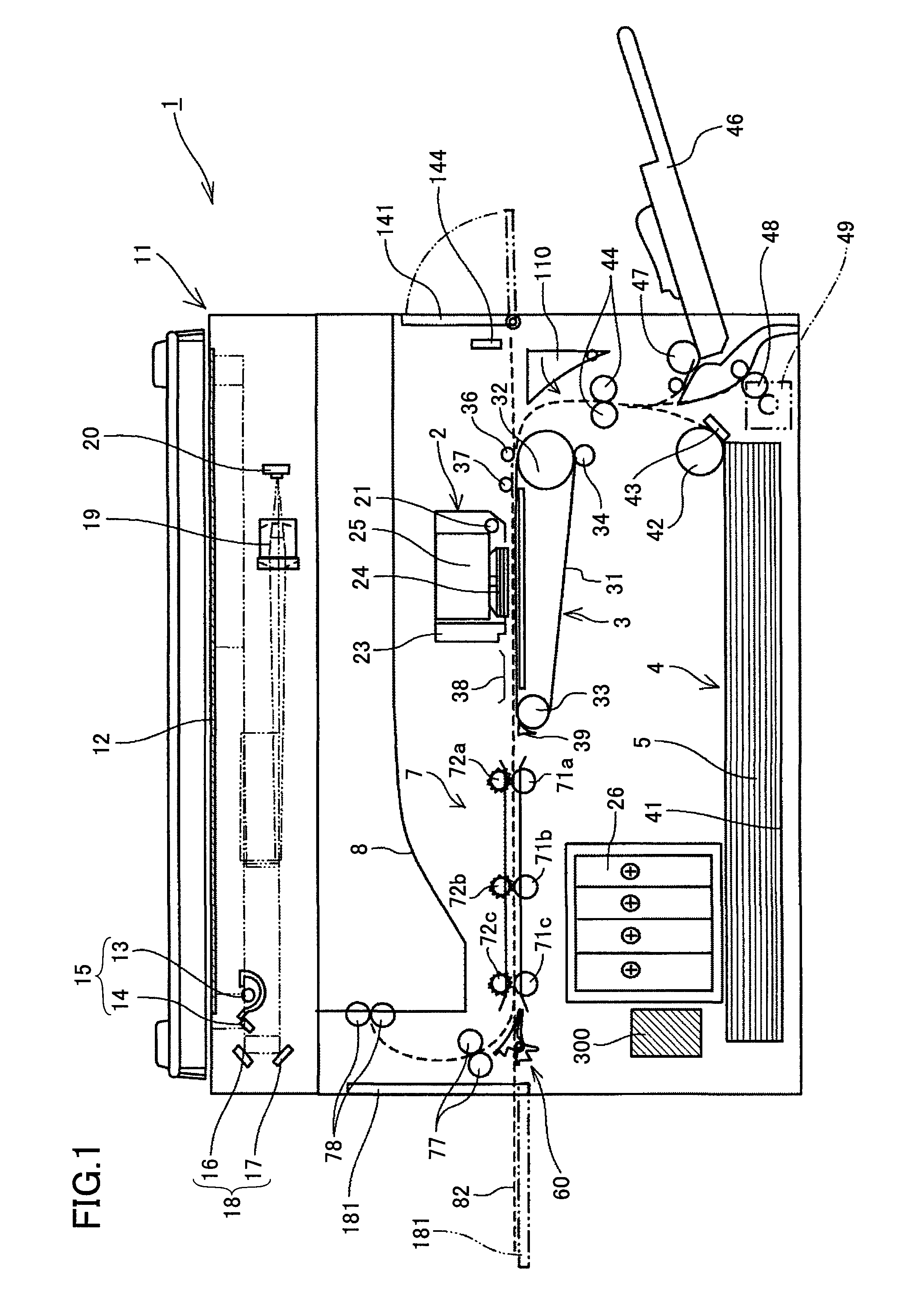
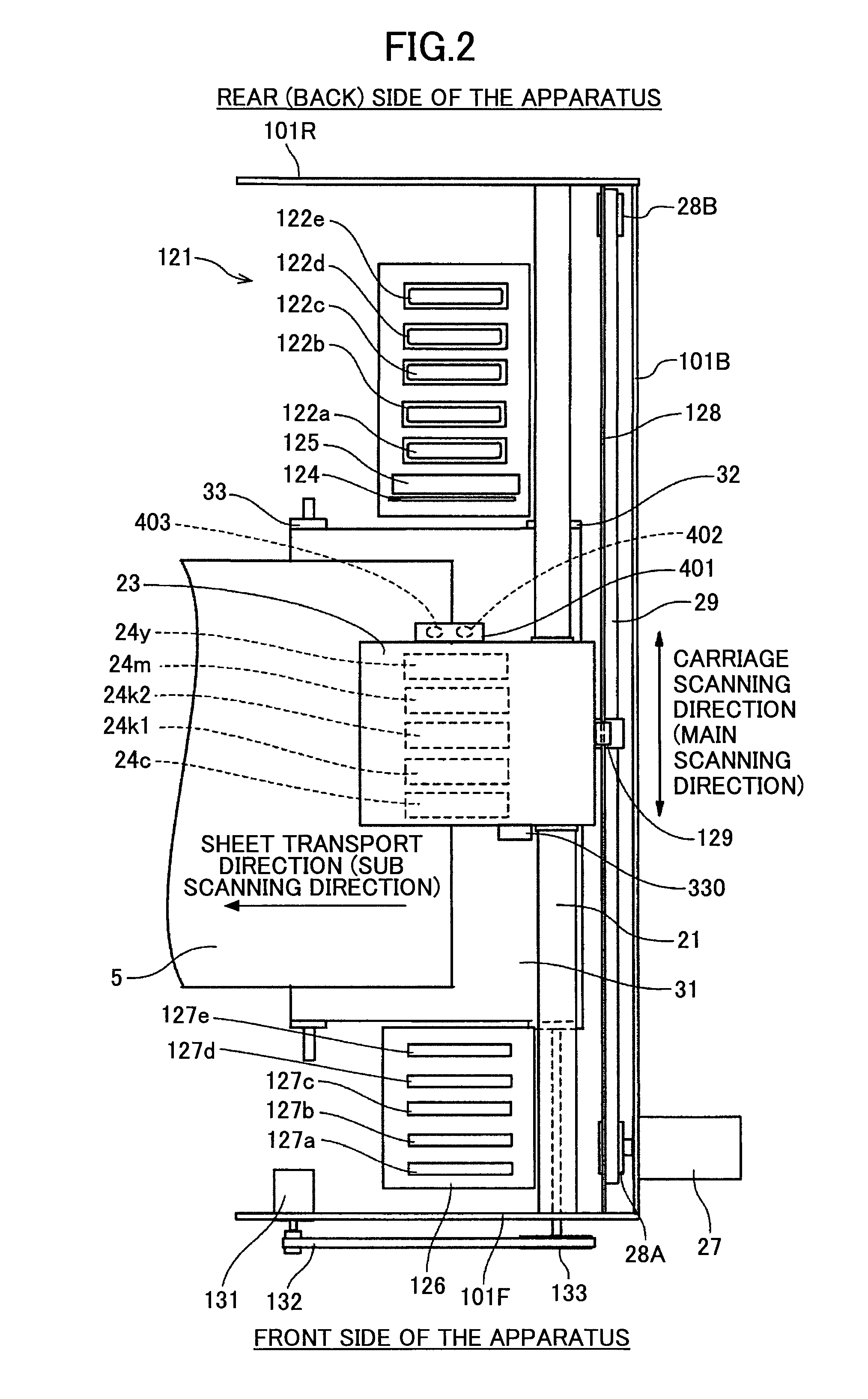
[0071]Preferred embodiments of the present invention are described hereinafter with reference to the accompanying drawings. An image forming apparatus of an embodiment of the present invention is described below with reference to FIGS. 1 through 3. FIG. 1 schematically illustrates a configuration of the image forming apparatus. FIG. 2 is a plan view illustrating an image forming unit 2 and a sub scanning direction transport unit 3 of the image forming apparatus. FIG. 3 is a side view illustrating the image forming apparatus.

[0072]The image forming apparatus includes, in an apparatus main body 1, the image forming unit 2 that forms an image on a sheet (recording medium) 5 and the sub scanning direction transport unit 3 that transports the sheet 5. In the image forming apparatus, sheets 5 are fed one by one from a sheet feed unit 4 including a sheet feed cassette 41 disposed at the bottom of the apparatus main body 1. The sheet 5 is transported by the sub scanning direction transport ...


PUM


Abstract

An image forming apparatus is provided with a carriage in which recording heads having nozzles for ejecting liquid droplets are mounted and is configured to form an image on a recording medium being transported. The image forming apparatus includes a pattern forming unit that forms an impact position displacement adjustment pattern formed of plural independent liquid droplets on a water repellent member; a reading unit that includes a light emitting unit for emitting light onto the adjustment pattern and a light receiving unit for receiving specular reflection light from the adjustment pattern; and an impact position correcting unit that corrects an impact position of a liquid droplet to be ejected from the recording head based on a read result by the reading unit. The reading unit is disposed on the carriage and is arranged close to the side of a guide member that guides movement of the carriage.

Description

BACKGROUND OF THE INVENTION[0001]1. Field of the Invention[0002]The present invention relates to an image forming apparatus including a recording head that ejects a liquid droplet; and a method for correcting a displacement of the impact position of a liquid droplet to be ejected from the recording head.[0003]2. Description of the Related Art[0004]Image forming apparatuses (e.g. printers, fax machines, copiers, and multifunction machines having functions of these machines) are known that perform image formation by ejecting a liquid (a recording liquid) such as ink onto a medium with use of, e.g., a liquid ejection device while transporting the sheet. The liquid ejection device comprises a recording head including a liquid ejection head (liquid droplet ejection head) for ejecting a droplet of the recording liquid (ink). It is to be noted that the term “medium” as used herein is hereinafter also referred to as a “sheet”, which may be paper or may be made of other materials. The terms ...

Claims


Application Information

Patent Timeline
Patent Type & Authority Applications(United States)
IPC IPC(8): B41J29/38B41J29/393
CPCB41J29/393B41J29/38B41J19/207
Inventor MORINO, TETSUSAWAYAMA, NOBORUKAWABATA, KENICHIYORIMOTO, MAMORUHIROTA, TETSUROHAGIWARA, TAKUMI
Owner RICOH KK
Why Eureka
Try Eureka