Pixel designs for multi-domain vertical alignment liquid crystal display

a liquid crystal display and multi-domain technology, applied in static indicating devices, instruments, non-linear optics, etc., can solve the problems of large color dispersion, narrow viewing angles, slow response times, etc., and achieve low cost fabrication processes and designs, wide viewing angles, and high contrast

Inactive Publication Date: 2008-09-18
KOPIN CORPORATION
View PDF40 Cites 10 Cited by
  • Summary
  • Abstract
  • Description
  • Claims
  • Application Information

AI Technical Summary

Benefits of technology

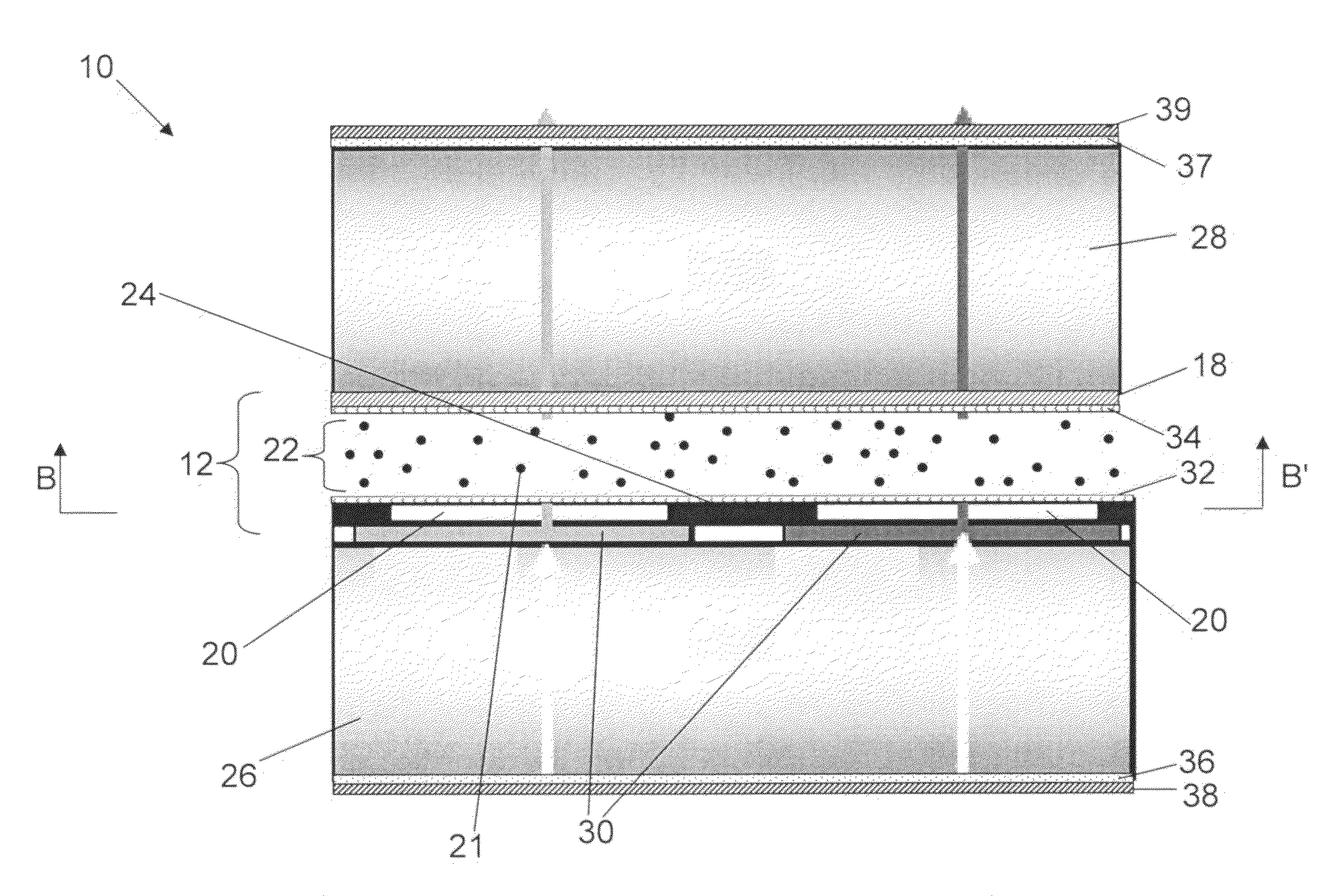
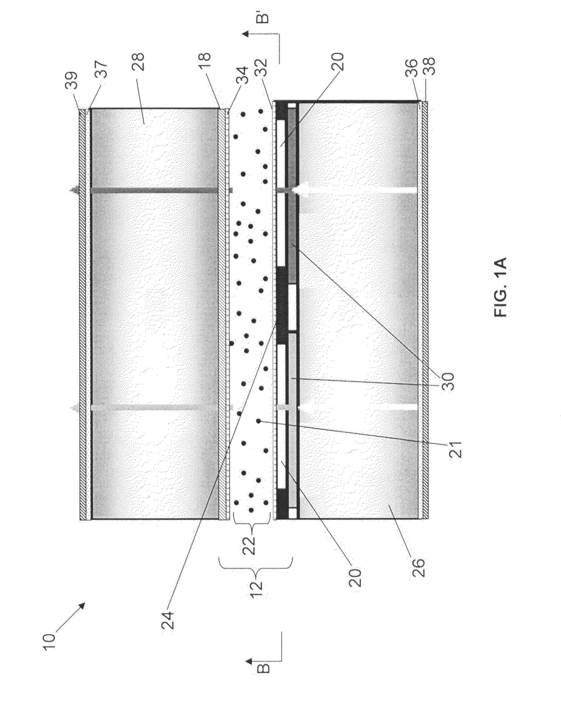
[0008]The MVA displays of the invention can employ a regular normal substrate, i.e., without special surface geometries, such as protrusions and ITO slits. This can result in significantly lower-cost fabrication processes and designs for manufacturing MVA displays, because the multi-domain LC response can be achieved without special surface geometries, such as protrusions and ITO slits. This is a substantial advantage, especially in microdisplays where such protrusions and ITO slits are extremely difficult to fit within the small pixel structures of the microdisplays, for example, MVA displays with about 15 μm×about 15 μm pixel size. The MVA displays of the invention can provide high contrast and wide viewing angles. The MVA displays of the invention, employing new color pixel designs, can be operated without substantial boundary stick and with substantially high optical transmission.

Problems solved by technology

The drawbacks of conventional LCDs include narrow viewing angles (±40° horizontally and −15° and +30° vertically), slow response times (about 40 ms), large color dispersion, and difficulty in manufacturing high quality LCDs based on a conventional rubbing process.
The conventional rubbing process is difficult to use for mass-production of multi-domain titled vertical electrically controlled birefringence LCD because of low-yield, high-cost multiple rubbing processes, unstable low-pre-tilt vertical alignment, and low contrast ratio for displays using a titled vertical LC alignment.
Also, these protrusions and ITO slits contribute to a high cost of production.
The combination of a protrusion surface with an ITO slit geometry provides another good control on the MVA-LCD, but requires a high cost process and also good alignment on the top and bottom substrates.

Method used


Image

  • Pixel designs for multi-domain vertical alignment liquid crystal display
  • Pixel designs for multi-domain vertical alignment liquid crystal display
  • Pixel designs for multi-domain vertical alignment liquid crystal display

Examples


example 1

Display Fabrication

[0068]Generally, the MVA displays of the invention can be fabricated as described above. In one example, spin-coated polyimide (PI) (Nissan vertical alignment PIs SE-1211 and RN-1566) as the LC alignment layers, Merck LC MLC-6884, and a cell gap of 2.0-4.0 μm were used for the MVA display fortification. 1 to 6% PI was spin coated at the speed of 1000-4000 RPM. The PI-coated wafers first pre-cure on hot plate at 85° C. for 5 minutes, then final-cure in a vacuum oven for 150-200° C. for 60 minutes. A vertical LC alignment without any pretilt angle was obtained with such PI alignment layers. LCDs with such a polyimide layer generally passed the prolonged reliability test of 72 hours exposure to 85° C. in 85% relative humidity. The fabricated MVA showed a normally black operation, with a wide viewing angle and high contrast ratio.

example 2

MVA Modeling

[0069]MVA display designs for a plurality of repeats can be modeled with both two-dimensional and three-dimensional models, such as Autronic 2-D LC Modeling software (2-D modeling) and Shintech 3-D LC Modeling software (3-D modeling). Geometrical optics approximation can be used for such modeling to make a fast estimation on the MVA electrical optical transmission. The modeling results can be used to understand and improve MVA operation, to help design the display pixel structure, and later compared to measurements from actual displays.

[0070]FIG. 11 shows 3-D calculated optical transmission vs. voltage of an MVA display having a plurality repeats as shown in FIGS. 2A and 2B (“M10 pixel design”). FIG. 12 shows 3-D calculated optical transmission vs. voltage of an MVA display having a plurality repeats as shown in FIGS. 4A and 4B (“M9 pixel design”). FIG. 13 shows 3-D calculated optical transmission vs. voltage of an MVA display having a plurality repeats as shown in FIGS....

example 3

Display Performance

A. Multi-Domain Creation

[0071]FIG. 7 shows a microphotograph of an image of an MVA display having a plurality repeats as shown in FIGS. 2A-2C with 1280×124×3 dot under a crossed polarizer geometry. As can be seen in FIG. 7, each dot showed four domains.

B. Transmission and Contrast Ratio

[0072]Five different MVA displays were prepared with a QVGA resolution (320×240 dots) with a dot size of 15 um×15 um and used for testing different backlight designs utilizing LED light sources, different combinations of diffusers (D) and brightness enhancement films (B): LED+D+B+B; LED+D+D+B+B; LED+B+D. Brightness and contrast ratio of the five displays were tested by Kopin Corporation. The applied voltage was 4.5 volts.

[0073]FIG. 14 shows measured brightness improvement for five displays for three different backlight designs: LED+D+B+B; LED+D+D+B+B; LED+B+D. The horizontal axis shows five different displays, with each curve showing the measured brightness improvement for 3 differe...


PUM

PropertyMeasurementUnit
pixel sizeaaaaaaaaaa
thicknessaaaaaaaaaa
thicknessaaaaaaaaaa

Abstract

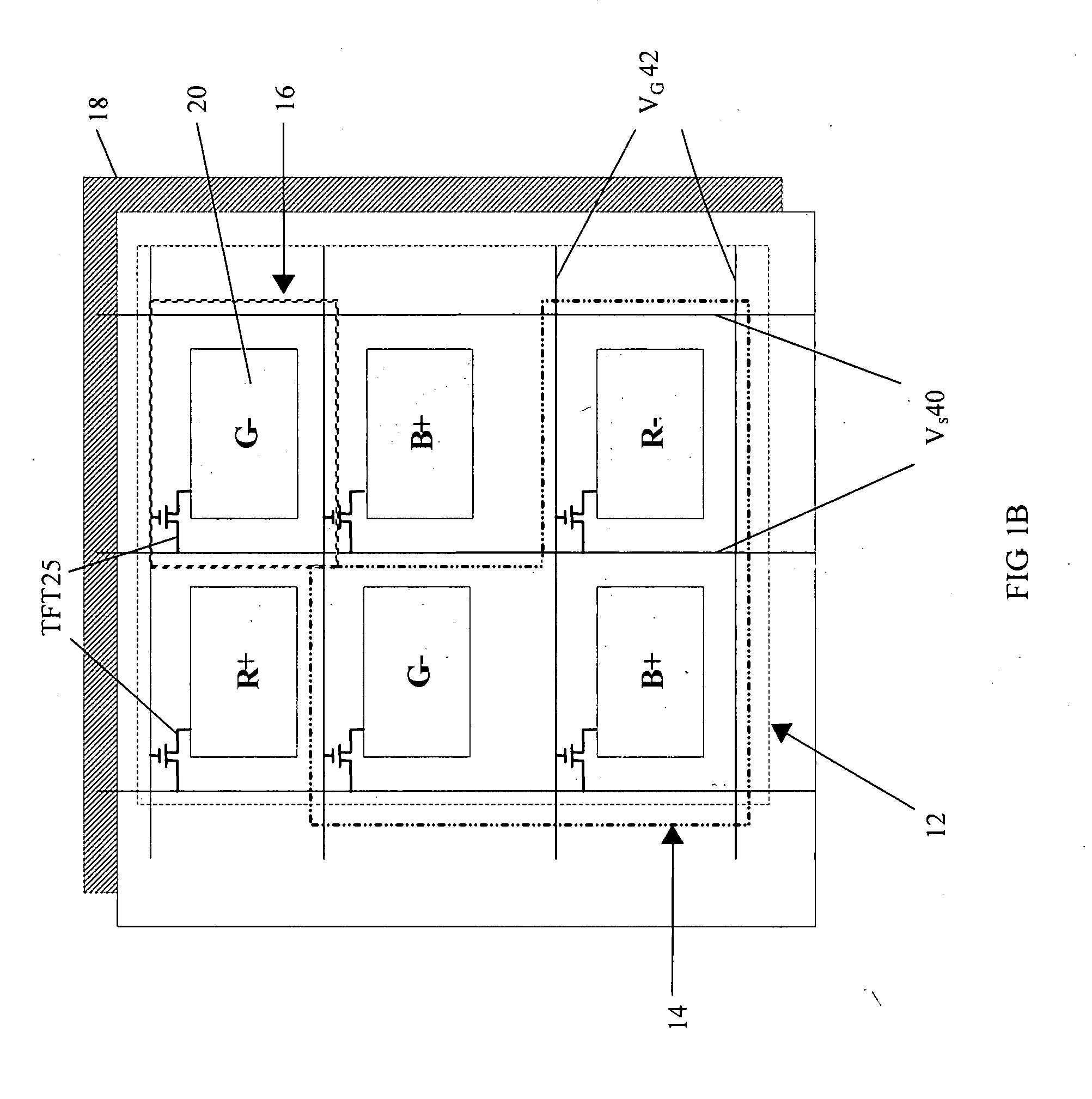
An MVA display includes a plurality of repeats between a first substrate and a second substrate, each of which includes at least one full color pixel, and a drive circuit for driving the plurality of repeats. Each full color pixel includes at least one color dot for each of red, blue and green. Color dots contiguous between at least two adjoining repeats in a row have different colors from each other. Each color dot includes a common electrode, a pixel electrode and a liquid crystal component having a negative dielectric anisotropy between the common electrode and the pixel electrode. The common electrode is common among at least a portion of the repeats. The drive circuit causes color dots contiguous between at least two adjoining repeats in a row to have different polarities from each other.

Description

GOVERNMENT SUPPORT[0001]The invention was supported, in whole or in part, by a grant, DAAB07-98-3-J032, from the U.S. Army Night Vision and Electronic Sensors Directorate (NVESD). The Government has certain rights in the invention.BACKGROUND OF THE INVENTION[0002]The market for liquid crystal displays (LCDs) is increasing rapidly, especially in areas of large-area liquid crystal displays and television applications. The requirements for these applications include high resolutions, very high contrast levels, wide symmetrical viewing angles, and fast response times. In addition, very high contrast levels with respect to different viewing angles, gray-scale inversion, colorimetry, and optical response of an LCD are important factors of high-quality LCDs. The cost associated with designing and manufacturing these LCDs, based on the above-mentioned requirements, also needs to be considered.[0003]Most conventional LCDs employ a 90° twisted nematic (TN) liquid crystal (LC) material in an L...

Claims


Application Information

Patent Timeline
Patent Type & Authority Applications(United States)
IPC IPC(8): G02F1/1343G02F1/1335G02F1/1337
CPCG02F1/133514G02F1/1393G02F2201/52G09G3/3614G09G2310/0281G09G2300/0443G09G2300/0447G09G2300/0452G09G2310/0251G09G3/3688
Inventor ONG, HIAP L.
Owner KOPIN CORPORATION
Why Eureka
Try Eureka