Surface flatness testing device and method thereof

a flatness testing and surface technology, applied in measurement devices, instruments, optically investigating flaws/contamination, etc., can solve the problems of increased operator errors, and low precision of surface flatness testing method

Inactive Publication Date: 2008-09-18
HONG FU JIN PRECISION IND (SHENZHEN) CO LTD +1
View PDF2 Cites 3 Cited by
  • Summary
  • Abstract
  • Description
  • Claims
  • Application Information

AI Technical Summary

Problems solved by technology

The surface flatness testing method using the thickness gauge and the standard platform is uncomplicated and relatively inexpensive.
However, the precision of this method is low because empirical data shows that the error using this method is, generally, about 0.02 millimeters.
Also, if many workpiece need to be check continuously, operator errors may increase.
Further, during testing, the testing surface of the workpiece makes contact with the standard platform and the thickness gauge and thus, the testing surface, the standard platform, and the thickness gauge are prone to abrasions.
Consequently, these abrasions will affect the appearance of the workpieces, the platform and the thickness gauge may wear out early.
This wearing out will affect the precision of the standard platform and the thickness gauge, resulting in an increase in testing errors.

Method used


Image

  • Surface flatness testing device and method thereof
  • Surface flatness testing device and method thereof
  • Surface flatness testing device and method thereof

Examples


Embodiment Construction

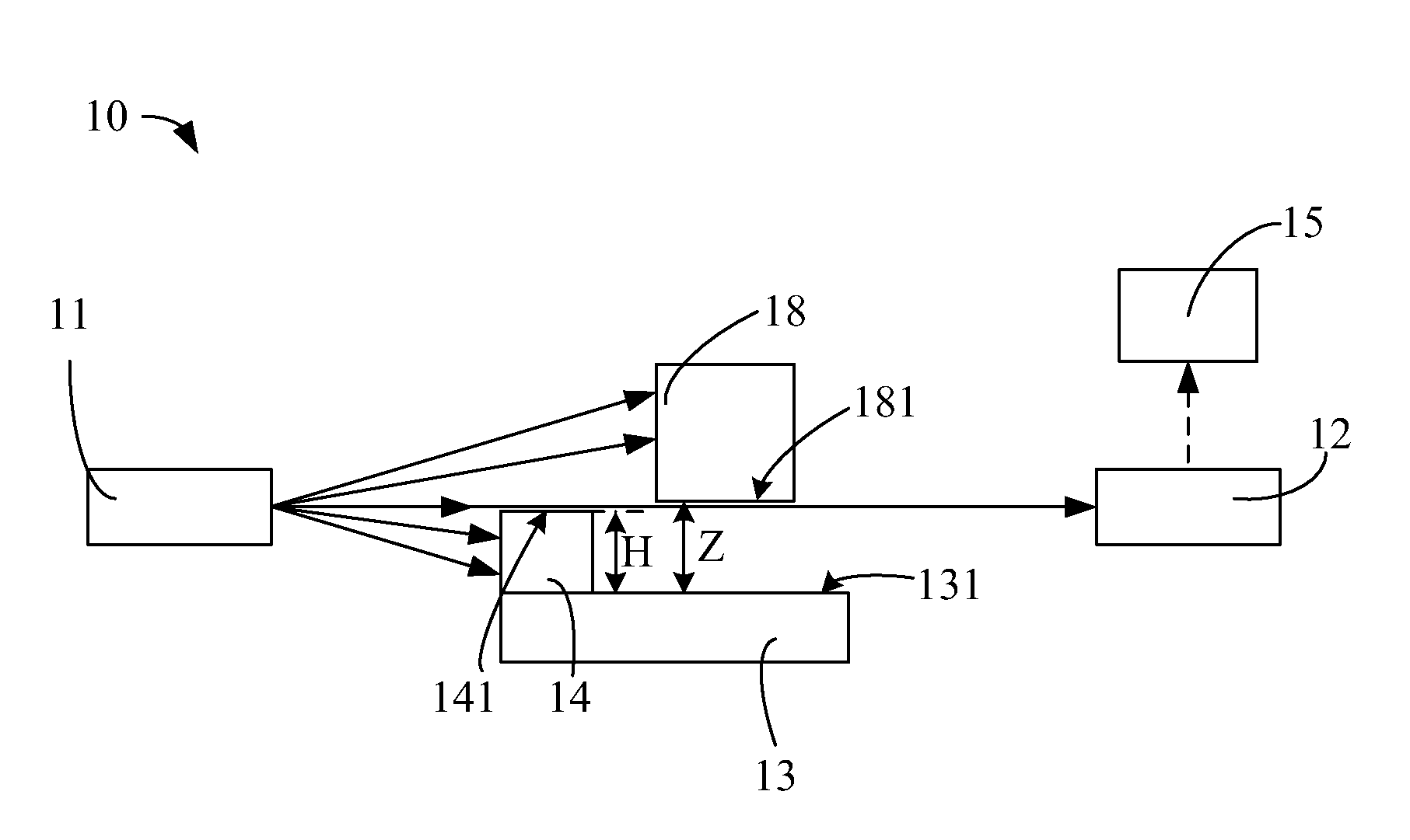
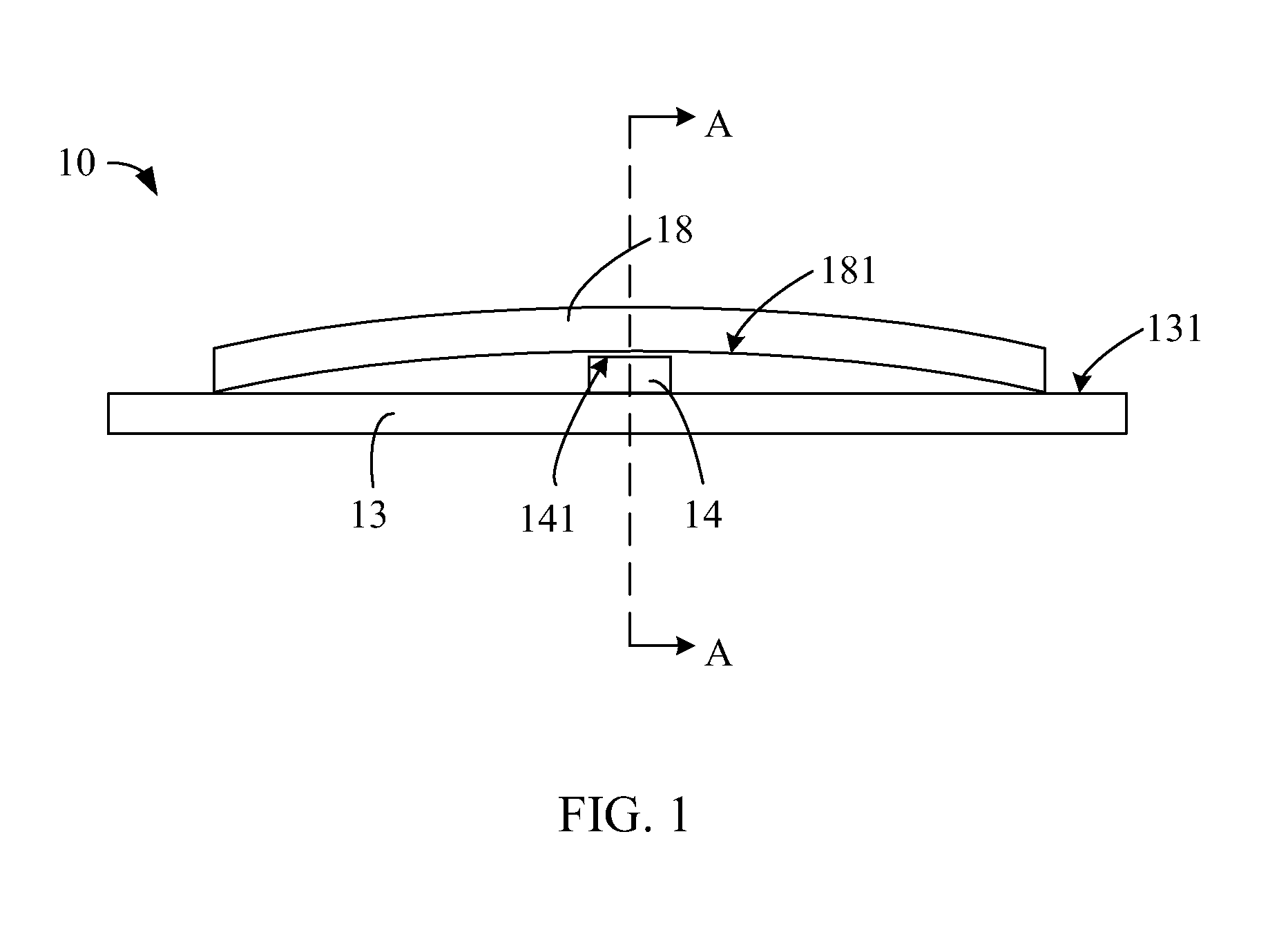
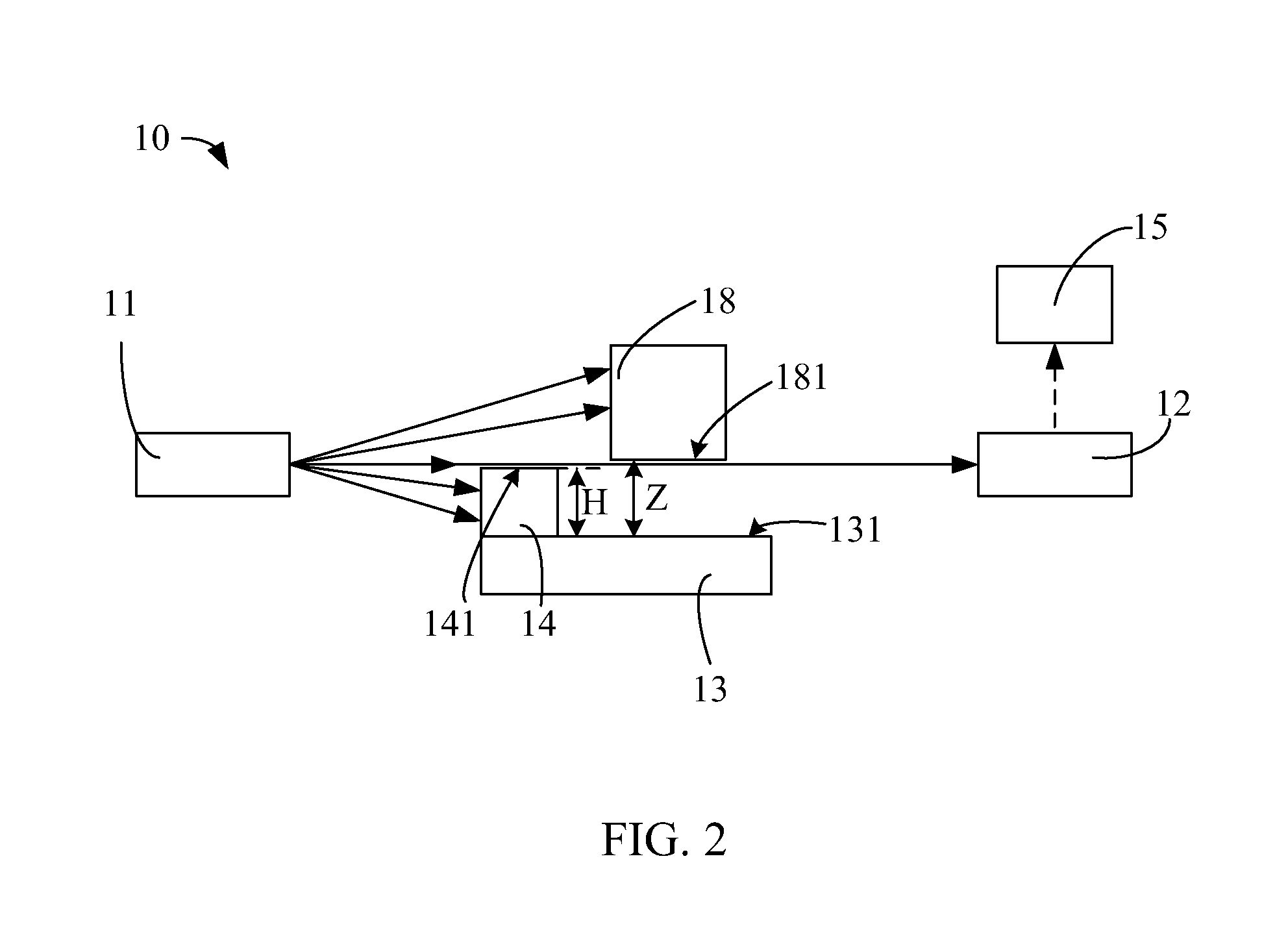
[0015]Referring to FIGS. 1 and 2, a surface flatness testing device 10 according to a first preferred embodiment of the present invention is shown. The surface flatness testing device 10 includes a light emitting unit 11, a light receiving unit 12, a platform 13, an adjusting unit 14, and a processing unit 15. The light receiving unit 12 faces the light emitting unit 11. In a described embodiment, the platform 13 is located between the light emitting unit 11 and the light receiving unit 12, and having the flat surface 131 receive workpiece 18 to test a flatness of a testing surface 181 of the workpiece 18. The axis that joins a light receiving center of the light receiving unit 12 and a light emitting center of the light emitting unit 11 is parallel to the flat surface 131 of the platform 13. The workpiece 18 can be a block, a sheet, or a frame. The testing surface 181 of the workpiece 18 is adjacent to the platform 13. The adjusting unit 14 can be also described as a flatness devia...


PUM

PropertyMeasurementUnit
surface flatness testingaaaaaaaaaa
surface flatnessaaaaaaaaaa
photosensitive resistanceaaaaaaaaaa

Abstract

An exemplary surface flatness testing device (10) includes a light emitting unit (11), a light receiving unit (12), a platform (13), an adjusting unit (14) and a processing unit (15). The light receiving unit faces the light emitting unit. The platform is located between the light emitting unit and the light receiving unit, which is configured for holding a workpiece (18) having a testing surface (181). The adjusting unit is disposed between the light emitting unit and the light receiving unit. The adjusting unit and the testing surface of the workpiece are controlling light from the light emitting unit to the light receiving unit. The processing unit is configured for processing signals from the light receiving unit. The present invention also provides a surface flatness testing method.

Description

BACKGROUND OF THE INVENTION[0001]1. Field of the Invention[0002]The present invention relates to surface flatness testing devices and methods, and more particularly to a non-contact surface flatness testing device and method.[0003]2. Discussion of the Related Art[0004]In the manufacturing industry, the surface flatness of a workpiece is important for reasons of aesthetic and for assembly with other workpieces. Thus the need for testing the surface flatness of workpieces is important. One method for testing surface flatness is by using a thickness gauge and a standard testing platform.[0005]Typically, a surface flatness testing method using a thickness gauge and a standard platform includes the following steps: placing a workpiece on the standard platform with the testing surface of the workpiece facing the standard platform, the flatness of the workpiece is determined by noting gaps between the surface of the workpiece under-test and the surface of the platform; the gaps are marked ...

Claims


Application Information

Patent Timeline
Patent Type & Authority Applications(United States)
IPC IPC(8): G01N21/88
CPCG01B11/306
Inventor JIANG, SHUNDONG, GUI-LI
Owner HONG FU JIN PRECISION IND (SHENZHEN) CO LTD
Why Eureka
Try Eureka