

Delay line interferometer having a movable mirror
- Summary
- Abstract
- Description
- Claims
- Application Information
AI Technical Summary
Benefits of technology
Problems solved by technology
Method used
Image

Examples
Embodiment Construction
[0042]The details of preferred embodiments and best mode for carrying out the ideas of the invention will now be presented. It should be understood that it is not necessary to employ all of the details of the preferred embodiments in order to carry out the idea of the invention. It should be further understood that the details of the preferred embodiments may be mixed and matched for carrying out the invention. Therefore, these details should be viewed for understanding the idea of the invention but should not to be read as limitations of the idea that is expressed in the below listed claims.
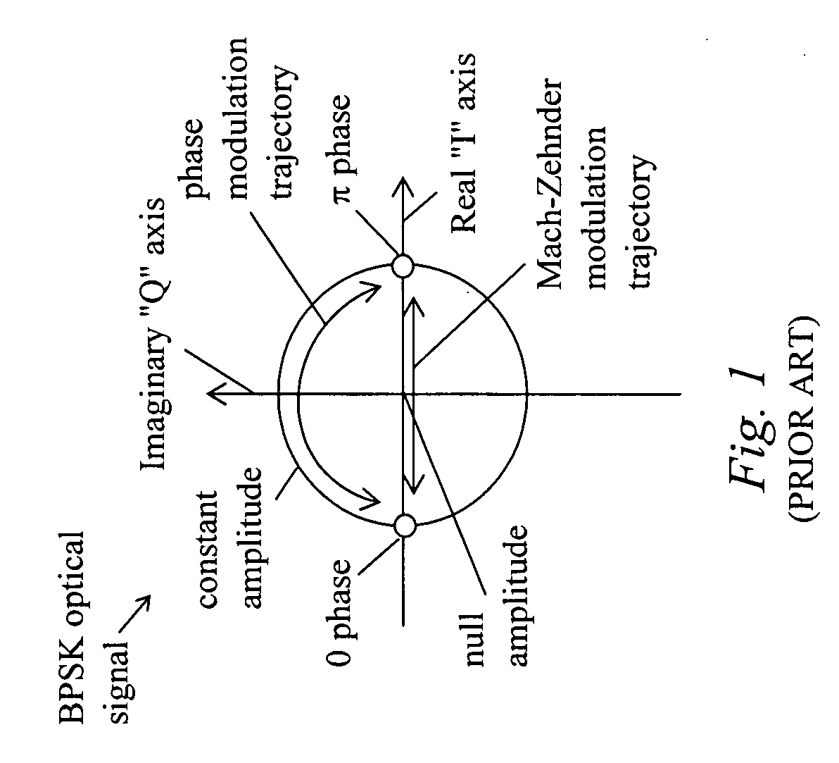
[0043]The preferred embodiments are described in terms of binary phase shift keyed (BPSK) signals using a differentially-encoded BPSK (DeBPSK, or DPSK) modulation format. However, the idea of the invention may be carried out with higher order modulation formats such as quadrature phase shift keyed (QPSK), 4QAM, 8PSK, 16QAM and so on. For example, the idea can be carried out with differentially-e...
PUM
 Abstract
Description
Claims
Application Information