Method and system for low power idle signal transmission in ethernet networks

a low-power idle and signal transmission technology, applied in the field of networkwork, can solve the problems of increasing power consumption in networks and networking devices, high data rate, etc., and achieve the effect of reducing power consumption

Active Publication Date: 2008-09-18
AVAGO TECH INT SALES PTE LTD
View PDF14 Cites 141 Cited by
  • Summary
  • Abstract
  • Description
  • Claims
  • Application Information

AI Technical Summary

Benefits of technology

[0018]FIG. 6 is a diagram illustrating an exemplary system enabled for reduced po...

Problems solved by technology

Additionally, higher data rates and more advanced circuitry ...

Method used


Image

  • Method and system for low power idle signal transmission in ethernet networks
  • Method and system for low power idle signal transmission in ethernet networks
  • Method and system for low power idle signal transmission in ethernet networks

Examples


Embodiment Construction

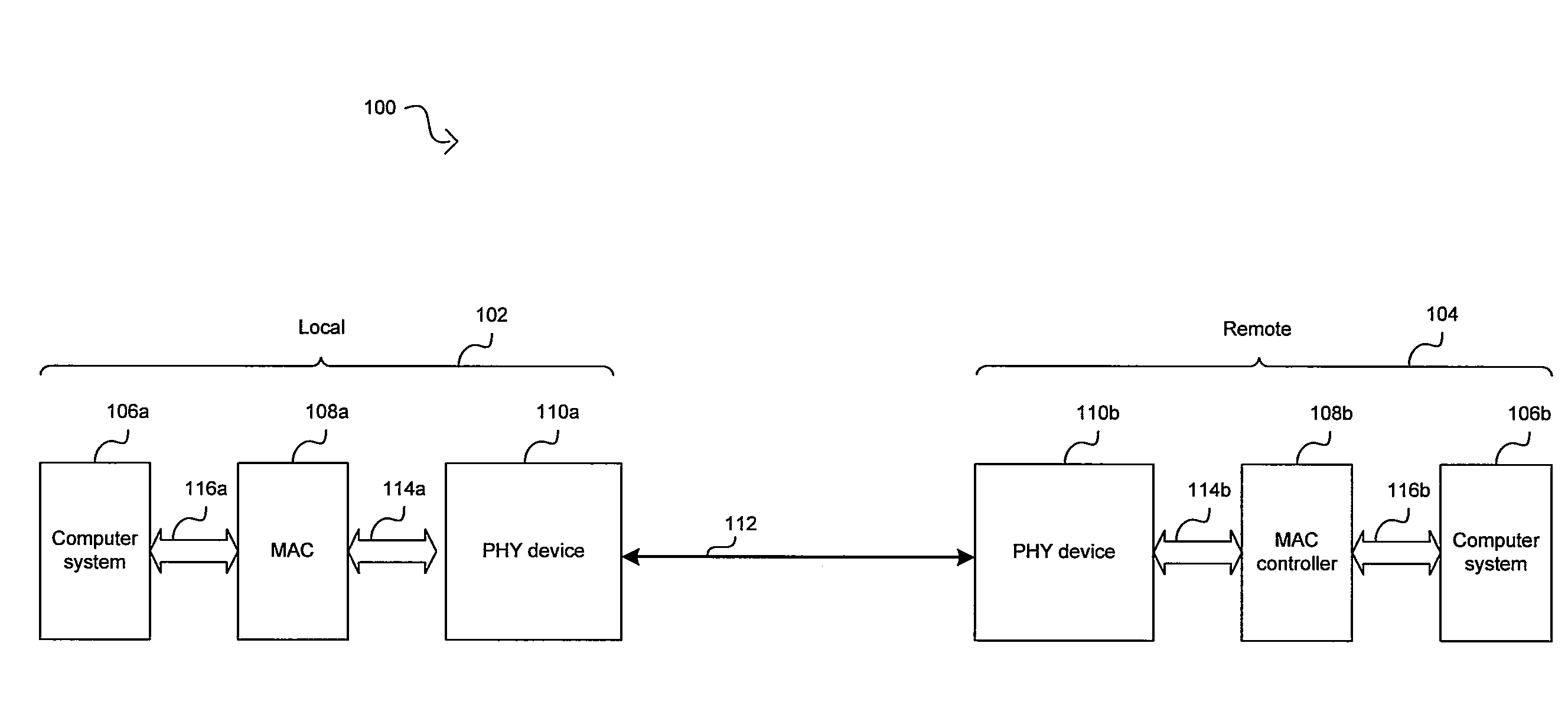
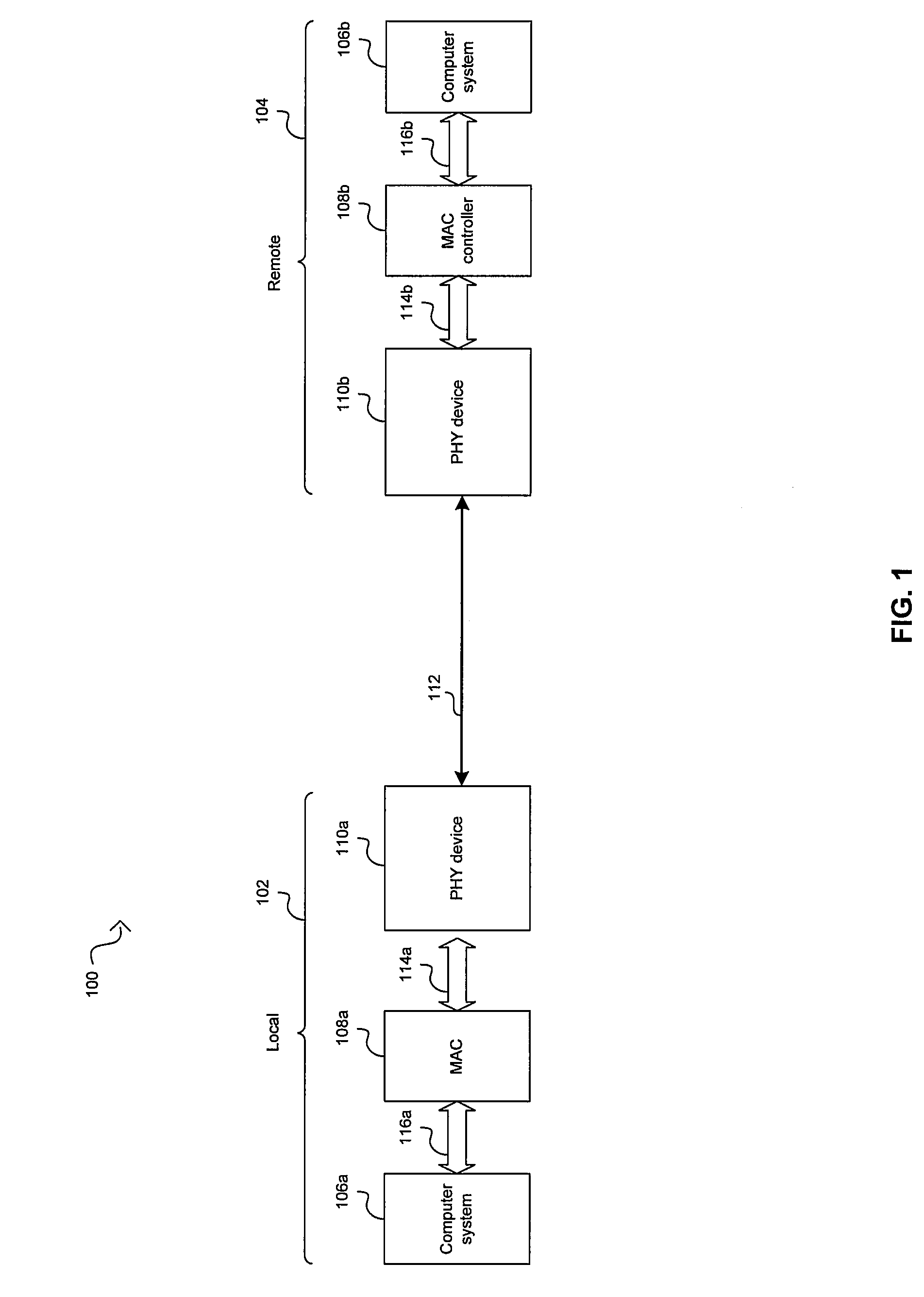
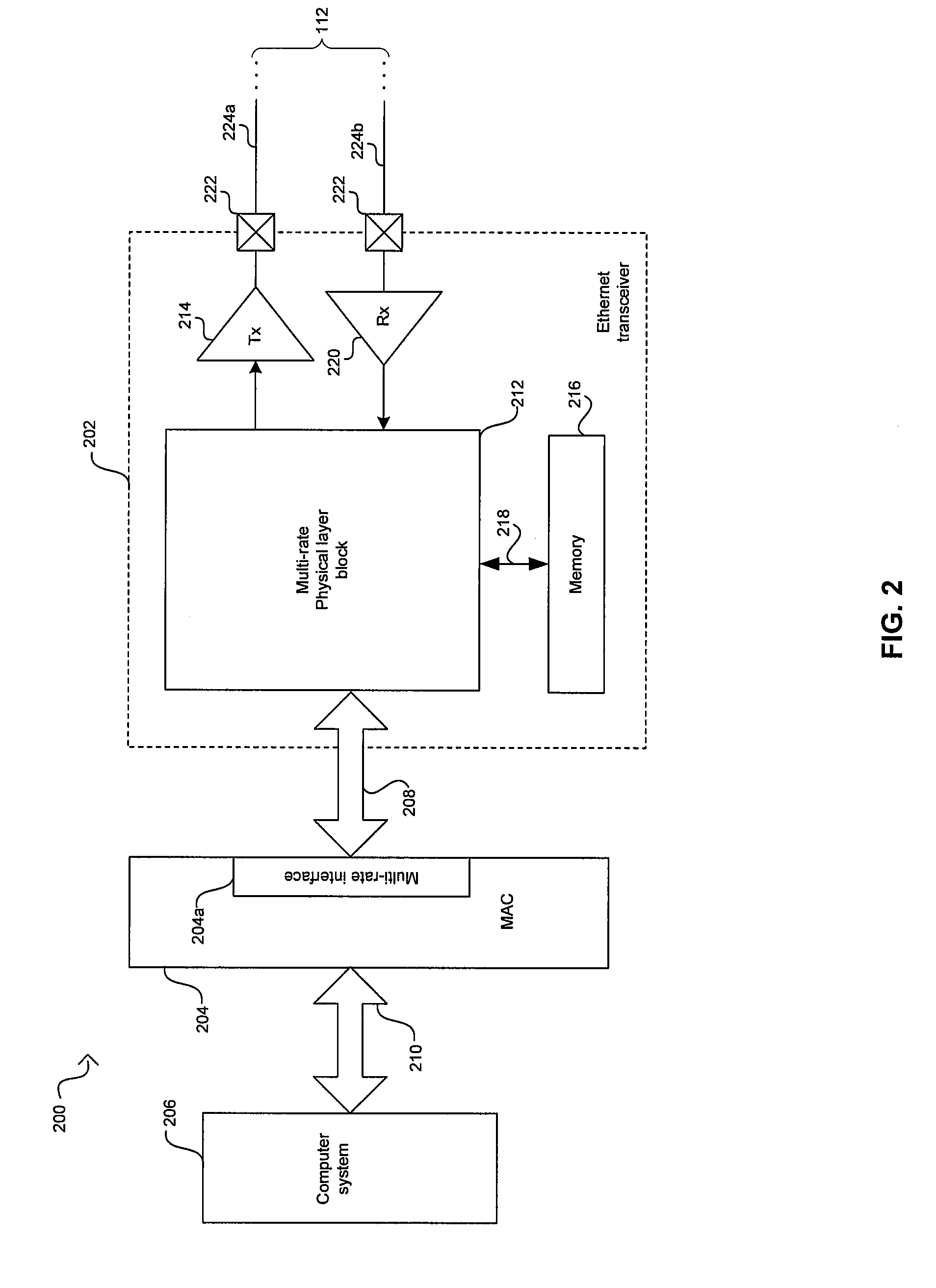
[0020]Certain embodiments of the invention may be found in a method and system for low power IDLE signal transmission. In this regard, during time periods between transmissions of actual data by a local Ethernet link partner, the local Ethernet Link partner may generate one or more signals, in place of a standard Ethernet IDLE signal, that enable synchronization between Ethernet link partners. In this manner, the generated signals may enable reducing power consumption as compared to standard Ethernet IDLE signals. Accordingly, link activity may be monitored to enable detecting periods when there may be no actual data for transmission and the generated signals may be transmitted. The generated signals may be transmitted at a reduced symbol rate as compared to standard Ethernet IDLE signals. The generated signals may be transmitted via fewer network links as compared to standard Ethernet IDLE signals. In this regard, one or more links may be designated, via logic, circuitry, and / or co...


PUM


Abstract

Aspects of a method and system for low power IDLE signal transmission in Ethernet networks are provided. In this regard, during time periods between transmissions of actual data by a local Ethernet link partner, the local Ethernet Link partner may generate one or more signals, in place of a standard Ethernet IDLE signal, that enable synchronization between Ethernet link partners. In this manner, the generated signals may enable reducing power consumption as compared to standard Ethernet IDLE signals. Accordingly, link activity may be monitored to enable detecting periods when there may be no actual data for transmission and the generated signals may be transmitted. The generated signals may be transmitted at a reduced symbol rate as compared to standard Ethernet IDLE signals. The generated signals may be transmitted via fewer network links as compared to standard Ethernet IDLE signals.

Description

CROSS-REFERENCE TO RELATED APPLICATIONS / INCORPORATION BY REFERENCE[0001]This patent application makes reference to, claims priority to and claims benefit from U.S. Provisional Patent Application Ser. No. 60 / 894,240 filed on Mar. 12, 2007.[0002]This patent application also makes reference to, claims priority to and claims benefit from U.S. Provisional Patent Application Ser. No. 60 / 917,870 filed on May 14, 2007.[0003]This application also makes reference to:U.S. patent application Ser. No. ______ (Attorney Docket No. 18600US02) filed on even date herewith;U.S. patent application Ser. No. ______ (Attorney Docket No. 18602US02) filed on even date herewith; andU.S. patent application Ser. No. ______ (Attorney Docket No. 18603US02) filed on even date herewith;[0004]Each of the above stated applications is hereby incorporated herein by reference in its entirety.FIELD OF THE INVENTION[0005]Certain embodiments of the invention relate to networking. More specifically, certain embodiments of ...

Claims


Application Information

Patent Timeline
IPC IPC(8): H04L12/56
CPCH04L12/413H04L12/40039Y02B60/31Y02B60/35H04L12/40136Y02D30/50
Inventor CONWAY, BRUCEPOWELL, SCOTT
Owner AVAGO TECH INT SALES PTE LTD
Why Eureka
Try Eureka