
Image forming method and process cartridge

Inactive Publication Date: 2008-09-18
RICOH KK
View PDF23 Cites 24 Cited by
  • Summary
  • Abstract
  • Description
  • Claims
  • Application Information

AI Technical Summary

Benefits of technology

[0017]Then a method is conceived where a recharging member is provided for recharging toner remaining on the latent electrostatic image bearing member to prevent contamination of the charging member for the latent electrostatic image bearing member. The method, however, can cause contamination by toner components because the recharging member for recharging toner remaining on the latent electrostatic image bearing member rubs against the toner.
[0018]The present invention has been accomplished to overcome the problems. An object of the present invention is to provide an image forming method, a process cartridge, and an image formation apparatus that recharges toner remaining on a latent electrostatic image bearing member for reusing the toner without collecting and discarding the toner; prevents contamination of a charging member for the latent electrostatic image bearing member and a recharging member; facilitates collecting of the remaining toner in a developing step; and provides excellent image stability and less deterioration in durability.
[0021]The present invention can provide an image forming method, a process cartridge, and an image formation apparatus that reuses toner remaining on a latent electrostatic image bearing member without collecting and discarding the toner, thereby reducing environmental loads; prevents contamination of a charging member for the latent electrostatic image bearing member and a recharging member; facilitates collecting of the remaining toner in a developing step; and provides excellent image stability and less deterioration in durability.

Problems solved by technology

As mentioned above, generation of adhered toner is perceived as a problem in the cleaner-less image forming method.

Method used

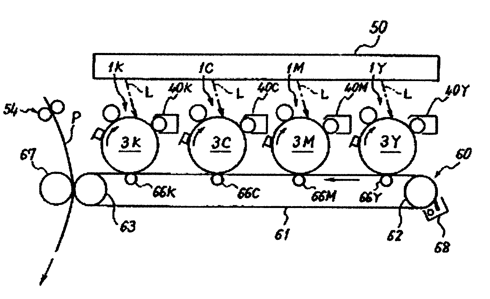

Image

  • Image forming method and process cartridge
  • Image forming method and process cartridge
  • Image forming method and process cartridge

Examples


example 1

Preparation of Pigment / Wax Dispersion (Oil Phase)>

[0159]To a vessel equipped with a stirrer bar and a thermometer, 378 parts of [polyester 1], 120 parts of paraffin wax (HNP9), 96 parts (releasing agent ratio: 80%) of a releasing agent (WAX) dispersing agent (styrene-polyethylene polymer, Tg: 73° C., number average molecular weight: 7,100), and 1,450 parts of ethyl acetate were placed, and the temperature was raised to 80° C. with stirring, maintained at 80° C. for 5 hours, and cooled to 30° C. in 1 hour. Next, 500 parts of [masterbatch 1], and 500 parts of ethyl acetate were placed into the vessel and mixed for 1 hour to obtain [initial material solution 1].

[0160]To a vessel 1,500 parts of the [initial material solution 1] was transferred, and carbon black and WAX were dispersed using a bead mill (Ultra Visco Mill manufactured by AIMEX CO., LTD.) under the conditions of liquid feed rate 1 kg / hr, disk circumferential speed of 6 m / sec, 0.5 mm zirconia beads filled to 80% by volume an...

examples 2 to 6

[0165]As shown in the evaluation results of toners in Tables 1-A and 1-B, the same processes as Example 1 were conducted except that conditions in Example 1 were changed in terms of the weight ratio (%) of the releasing agent dispersing agent based on the solid content of the releasing agent, the amount of the modified laminar inorganic mineral, and the amount of the external additive to obtain the developers of Examples 2 to 6.


PUM


Abstract

An image forming method, including recharging untransferred toner remaining on a latent electrostatic image bearing member by using a recharging member to remove the untransferred toner from the latent electrostatic image bearing member, wherein the recharging member is a conductive member a surface of which has a contact angle of 108° or more with pure water and a Shore D hardness of 50 to 65; the coverage of the surface of the toner by an external additive is 150% or less; and a releasing agent peak ratio obtained by ATR method is 0.02 to 0.1.

Description

BACKGROUND OF THE INVENTION[0001]1. Field of the Invention[0002]The present invention relates to an electrophotographic image forming method, an electrophotographic process cartridge, and an electrophotographic image formation apparatus. The present invention specifically relates to an image forming method used for copying machines, printers, and the like that apply electrophotographic techniques using a toner for developing electrostatic charge. The present invention particularly relates to an image forming method, a process cartridge, and an image formation apparatus that enables reusing a toner remaining on a latent electrostatic image bearing member without collecting and discarding the toner; preventing contamination of the latent electrostatic image bearing member recharging member; easy collecting of the remaining toner in a developing step; and excellent image stability.[0003]2. Description of the Related Art[0004]A conventionally and widely used method for collecting a tone...

Claims


Application Information

Patent Timeline
IPC IPC(8): G03G13/04G03G15/00
CPCG03G21/0047G03G2221/0005G03G21/0058
Inventor KADOTA, TAKUYANOZAKI, CHIYOSHINOZAKI, TSUYOSHIMURAKAMI, HIROYUKIMATSUMOTO, MITSUYOYAMAMOTO, ATSUSHIFUJITA, TETSUMARUNAGATOMO, YUJI
Owner RICOH KK
Learn More