
Developing device and image forming method using one component developer, and process cartridge using the developing device

a technology of developing device and image forming method, which is applied in the direction of electrographic process apparatus, instruments, optics, etc., can solve the problems of abnormal image formation, inability to form developer layer having a predetermined thickness and a predetermined charge, and inability to charge toner particles well

Inactive Publication Date: 2008-09-18
RICOH KK
View PDF19 Cites 34 Cited by
  • Summary
  • Abstract
  • Description
  • Claims
  • Application Information

AI Technical Summary

Benefits of technology

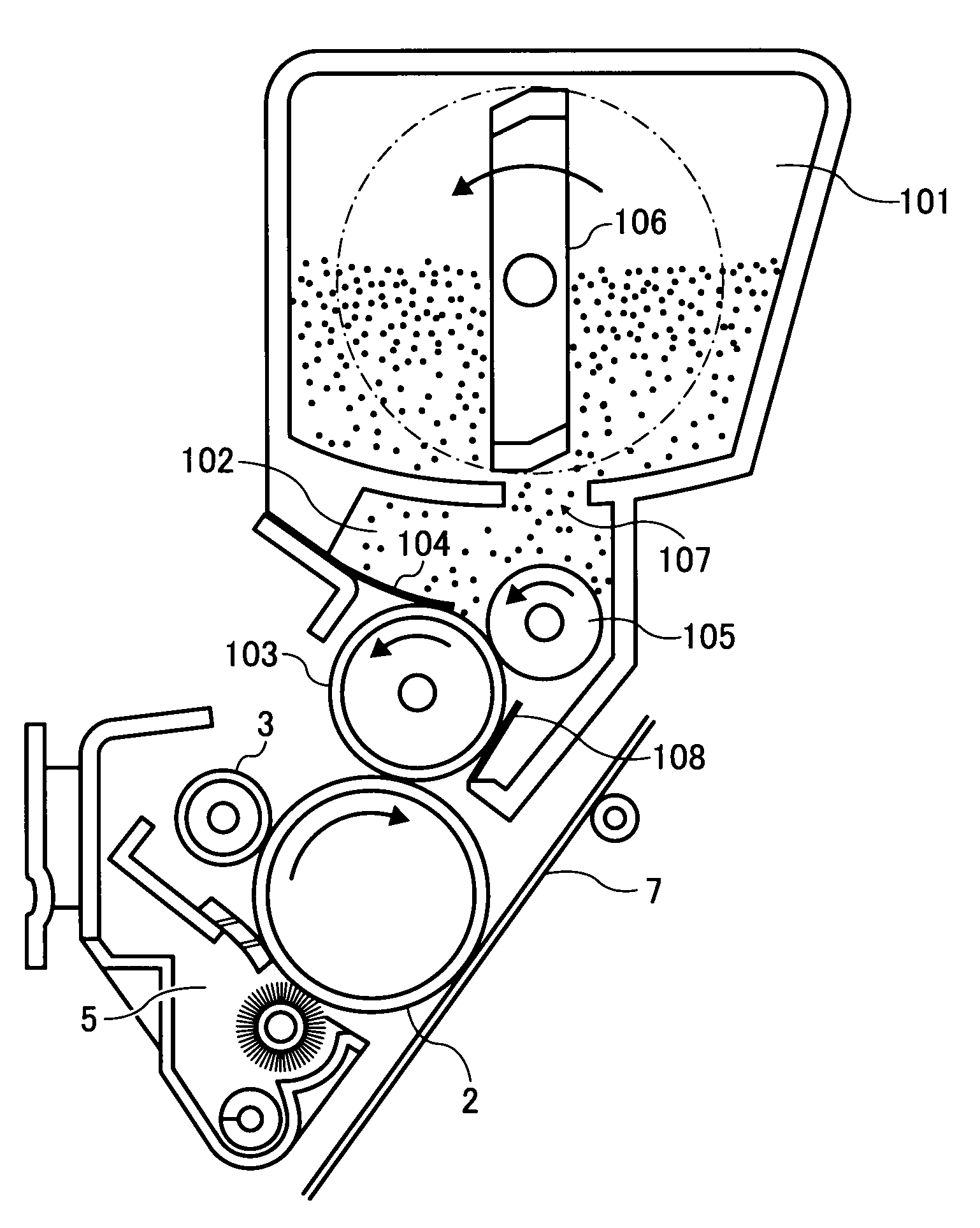
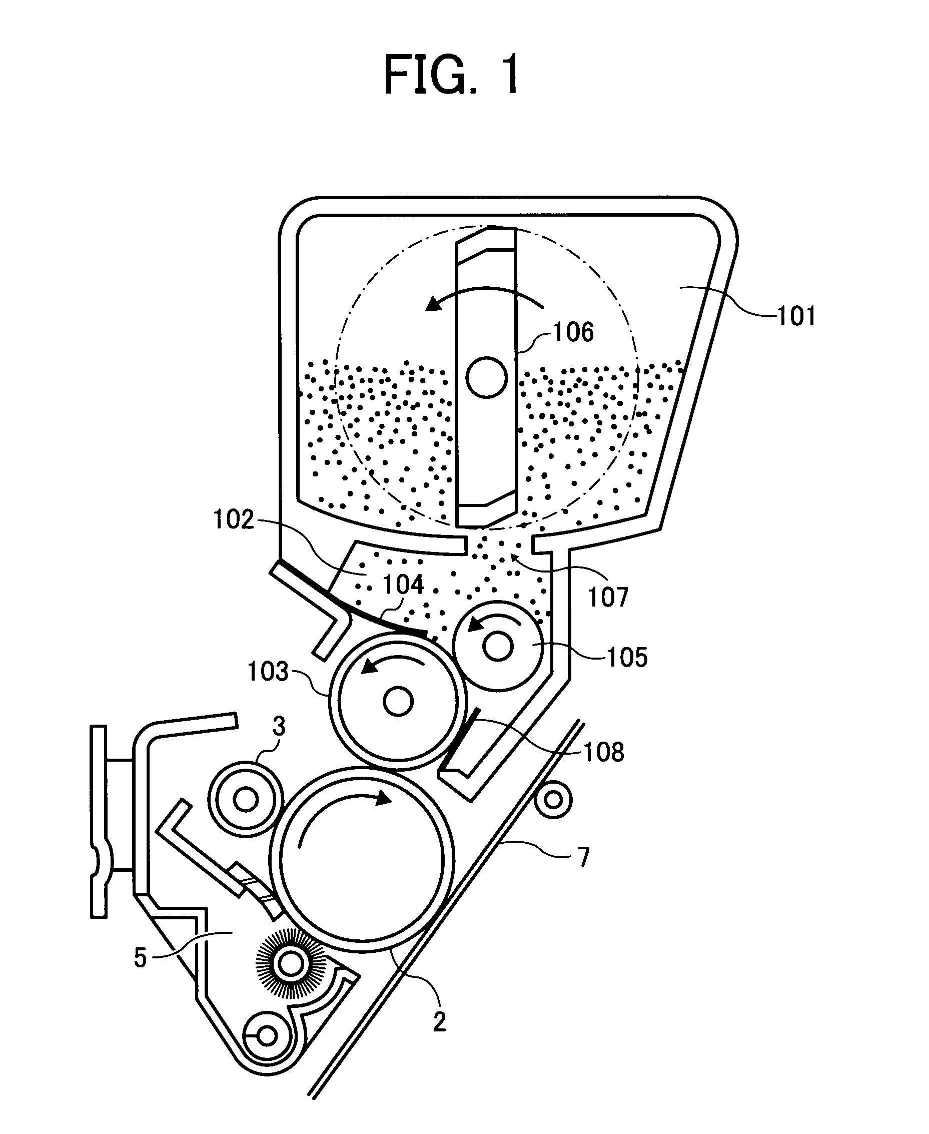
The present invention provides a developing device with a one component developer that includes a binder resin, wax, and colorant. The developing device satisfies certain relationships to achieve efficient development of toner images. The invention also provides a process cartridge with the developing device and an image forming apparatus for detachable attachment. The image forming method involves forming a layer of one component developer on a developing roller and developing an electrostatic image on an image bearing member with the developer layer. The technical effects of the invention include improved quality and efficiency of toner image development.

Problems solved by technology

However, heat roller fixing devices often cause an offset problem in that part of a toner image formed on a sheet of a receiving material is transferred to a fixing member of the fixing devices, and the transferred toner image is retransferred to the receiving material sheet and / or the next receiving material sheet, resulting in formation of abnormal images.
In addition, toner particles are also adhered to the wax on the developer layer forming blade, resulting in occurrence of a problem in that a developer layer having a predetermined thickness and a predetermined charge cannot be formed.
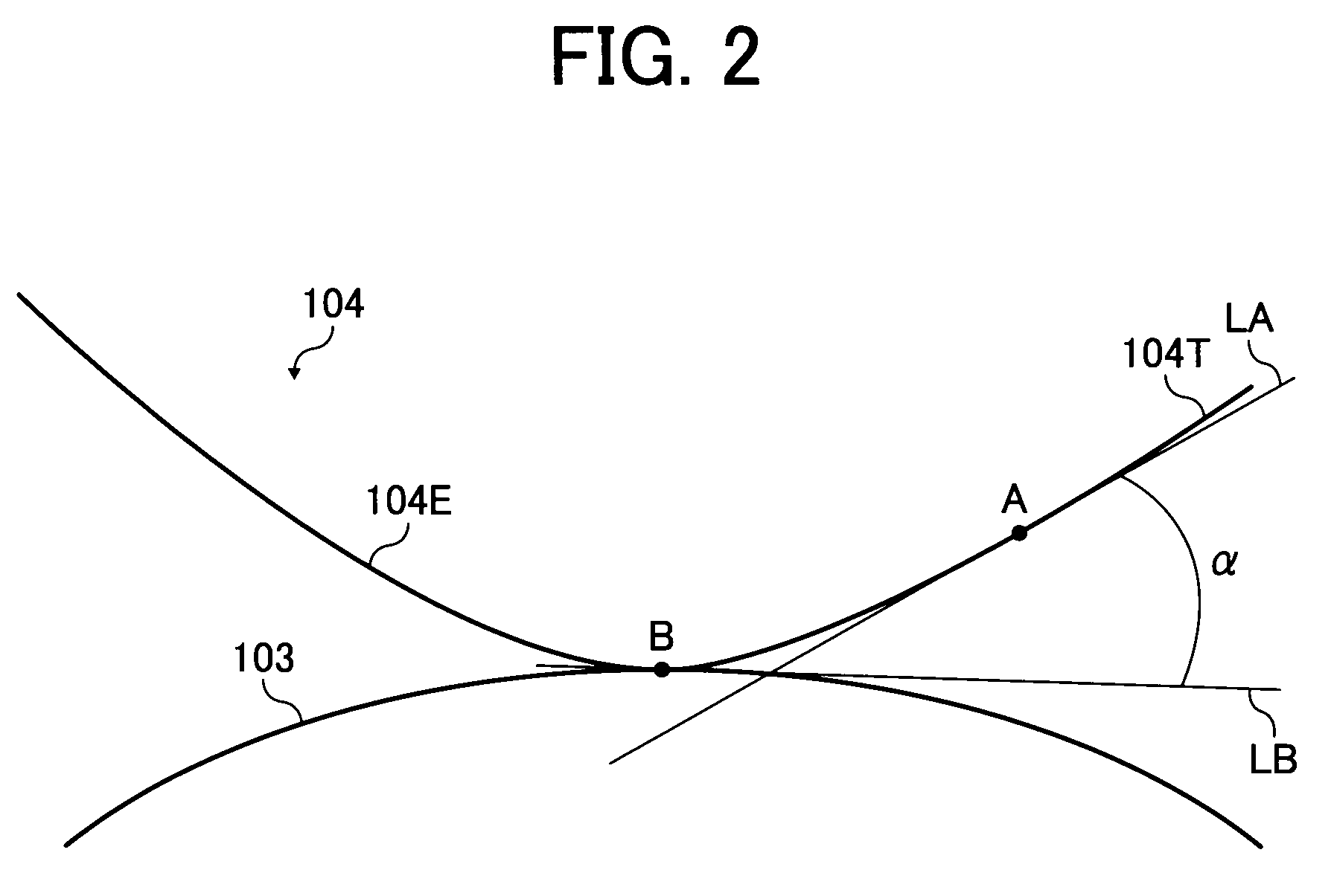
In contrast, when the angle (α) is too low, the amount of the toner particles passing through the nip increases due to the pressure of the toner, and thereby the toner particles cannot be well charged, resulting in occurrence of a background development problem in that the background of images is soiled with the toner particles.
However, since the developer layer forming blade is not controlled, the technique cannot definitely settle the wax adhesion problem.

Method used


Image

  • Developing device and image forming method using one component developer, and process cartridge using the developing device
  • Developing device and image forming method using one component developer, and process cartridge using the developing device
  • Developing device and image forming method using one component developer, and process cartridge using the developing device

Examples


preparation examples 1-3

Toner Preparation Examples 1-3 and Comparative Examples 1-10

Preparation of First Binder Resin

[0076]The following components were contained in a dropping funnel.

Vinyl monomersStyrene600 gButyl acrylate110 gAcrylic acid 30 gDicumylperoxide 30 g(polymerization initiator)

[0077]The following components were contained in a four necked 5-liter flask equipped with a thermometer, a stainless stirrer, a condenser, and a nitrogen feed pipe.

Monomers for polyester resinPolyoxypropylene(2.2)-2,2-bis(4-1230 g hydroxylphenyl)propanePolyoxyethylene(2.2)-2,2-bis(4-290 ghydroxylphenyl)propaneIsododecenyl succinic anhydride250 gTerephthalic acid310 g1,2,4-benzenetricarboxylic acid anhydride180 gDibutyl tin oxide (esterification catalyst) 7 gParaffin wax120 g(melting point: 73.3° C., halfwidth of absorption peak inDSC curve: 4° C., weightratio of monomers to wax: 100:4)

[0078]The components in the four-necked flask were heated to 160° C. by a mantle heater while agitated with the stirrer under a nitrogen...


PUM


Abstract

A developing device including a developing roller and a developer layer forming member for forming a layer of a one component developer on the roller. The developing device satisfies the relationships (1) 20<X<65−14α, and (2) 12.7α−25>Q / M>13.1α−44.5, wherein X represents the ratio (% by weight) of the wax present on the surface of the developer to the total of the wax therein; α represents the angle formed by a tangent line to the member at a point B, which is the center of the contact zone of the member contacted with the roller, and another tangent line at a point A thereof 0.5 mm apart from the point B toward the tip of the member, wherein α is 0 to π / 2 radian; and Q / M represents the charge quantity (μC / g) of the toner per unit weight.

Description

BACKGROUND OF THE INVENTION[0001]1. Field of the Invention[0002]The present invention relates to a developing device using a one component developer. In addition, the present invention also relates to an image forming method using a one component developer and a process cartridge using the developing device.[0003]2. Discussion of the Background[0004]Recently, a need exists for small-sized and low-cost laser printers for use in a low-end market. It is essential to use a fixing device (particularly a heat roller fixing device) without an oil applicator for small-sized printers. However, heat roller fixing devices often cause an offset problem in that part of a toner image formed on a sheet of a receiving material is transferred to a fixing member of the fixing devices, and the transferred toner image is retransferred to the receiving material sheet and / or the next receiving material sheet, resulting in formation of abnormal images. In order to prevent occurrence of the offset problem,...

Claims


Application Information

Patent Timeline
Patent Type & Authority Applications(United States)
IPC IPC(8): G03G13/06G03G15/08
CPCG03G15/0812
Inventor FUWA, KAZUOKIHAGI, MASAYUKIMIKURIYA, YOSHIHIROYASUNAGA, HIDEAKIKATOH, HIROAKISEKIGUCHI, YOSHITAKAOGAWA, SATOSHI
Owner RICOH KK
Learn More