
Narrow Dental Implant and Associated Parts

a dental implant and a technology for reducing the diameter of the implant, applied in the field of dental implants, can solve the problems of insatiable use of implants with conventional diameters, inconvenient use of implants, and large external diameters for the requirements of applications

Inactive Publication Date: 2008-09-18
BIOTECHNOLOGY INST I MAS D SL
View PDF7 Cites 32 Cited by
  • Summary
  • Abstract
  • Description
  • Claims
  • Application Information

AI Technical Summary

Benefits of technology

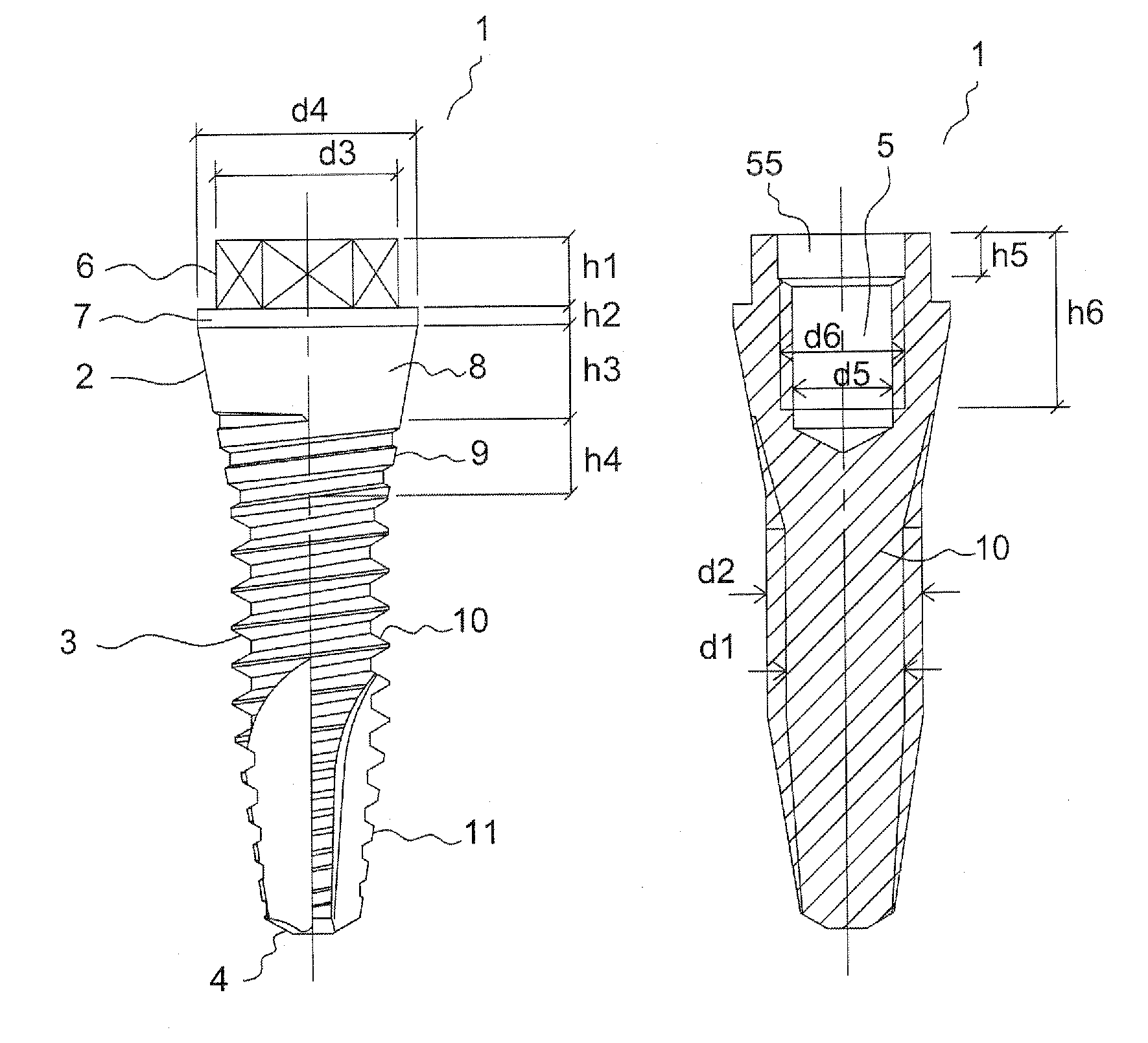
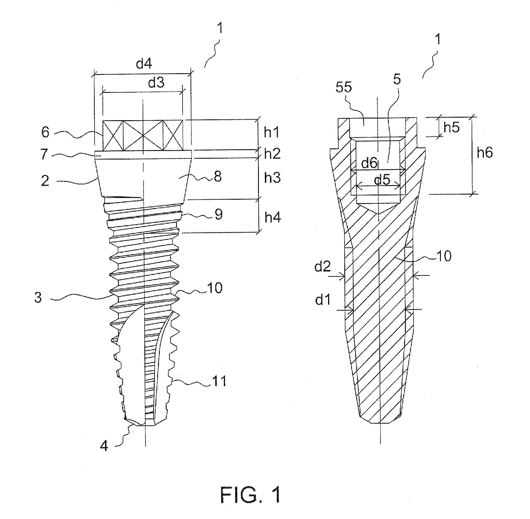
[0019]Similarly to conventional implants, the dental implant according to the invention comprises a head, a threaded body and an apical end or apex. The implant is solid and comprises a blind threaded hole for the connection of a screw. The dental implant according to the invention is categorised as ‘narrow’ because one of its essential innovative characteristics is that it presents a reduced thickness or diameter in comparison with prior art implants. This innovative characteristic is accompanied by other additional changes in the design of the implant, so that the reduction of the thickness of the implant does not reduce the implant's robustness, preloading capability, ability to prevent the appearance of breakage points, and other necessary qualities.
[0051]An additional advantage offered by the narrow dental implant according to the invention is that the lower conical threaded area, being so narrow, enables the implant to present a greater penetration capability and even allows it to be fitted using only a single start drill. In addition, as the lower threaded area is both conical and narrow, the implant itself can perform the crest expansion, thereby reducing the number of procedures and the total operating time required in certain applications or scenarios.

Problems solved by technology

In other words, their external diameters are too large for the requirements of the application.
This is extremely uncomfortable and unpleasant as the dentures are disposed in such a way that they press on the implants (if the implants are visible) or on the gums covering the implants (if the implants are hidden).
A second application in which the use of implants with conventional diameters is not entirely satisfactory is that in which an implant is installed in a narrow area of a maxillary bone crest.
These processes involve complex surgery, besides having to wait an additional time for the widened crest bone to regenerate or for the graft to settle.
A third application in which the use of implants of conventional diameters is not entirely satisfactory is that in which various implants are to be installed in adjacent narrow and wide areas of a hybrid maxillary bone.
The drawback with this system is that only one or two dental implants must endure the local mechanical forces of all the prosthetic elements that they carry, these mechanical forces being of all types and directions.
As a consequence, the implants can easily fail, leading to the appearance of a certain mobility in the implants or in the prosthodontic components connected to the implants.
A fourth application in which the use of implants of conventional diameters is not entirely satisfactory is that in which a dental implant and a dental prosthesis are to be installed in a maxillary area, be it wide or narrow, with the requirement that the dental prosthesis be positioned at the same time as the implant is fitted, in other words, without waiting weeks or months for the osseointegration of the implant in the maxillary bone to occur.
It represents a challenge in oral surgery due to its difficulty, mainly in terms of preventing faults such as the anchoring or installation of the implant working loose.
As a result, separating the impression copings from the transpehitelial abutments, and therefore extracting the impression, may be difficult or impossible if the implants are disposed at very different angulations.
This inappropriate and rough handling of the impression undermines the initial stability of the recently fitted implants, thus jeopardising the end result of the surgery.
Having the implants disposed at very different angulations can also be an obstacle in other steps and procedures of the treatment, e.g. when trying to connect the dental prostheses to the implants.

Method used


Image

  • Narrow Dental Implant and Associated Parts
  • Narrow Dental Implant and Associated Parts
  • Narrow Dental Implant and Associated Parts

Examples


Embodiment Construction

[0018]In order to achieve the aforementioned objectives, the invention defines a narrow dental implant and a series of associated components or parts related to said implant.

[0019]Similarly to conventional implants, the dental implant according to the invention comprises a head, a threaded body and an apical end or apex. The implant is solid and comprises a blind threaded hole for the connection of a screw. The dental implant according to the invention is categorised as ‘narrow’ because one of its essential innovative characteristics is that it presents a reduced thickness or diameter in comparison with prior art implants. This innovative characteristic is accompanied by other additional changes in the design of the implant, so that the reduction of the thickness of the implant does not reduce the implant's robustness, preloading capability, ability to prevent the appearance of breakage points, and other necessary qualities.

[0020]The narrow dental implant according to the invention ...


PUM


Abstract

New platform comprising a dental implant (1) and associated parts characterised in that both the implant (1) and the associated parts have a reduced diameter that makes them suitable for certain applications, particularly for treating narrow areas of a bone crest. In order to be able to achieve a dental implant (1) and associated parts that are narrow but still robust and reliable. certain characteristics and geometrical forms of the dental implant (1) and the associated parts have been readjusted or optimized.

Description

TECHNICAL FIELD [0001]The invention relates to a dental implant and other parts associated to it that enable the fitting or installing of one or more dental prosthesis or artificial teeth in the maxillary bone of a patient.PRIOR ART [0002]As is well known in the prior art, dental implants are generally threaded parts that are inserted into the maxillary bone of a patient and to which, following a process of osseointegration or bone integration of the implant in said maxillary bone (or even before osseointegration takes place), a dental prosthesis with one or more artificial teeth is affixed. To achieve this, a series of associated parts are needed. These associated parts enable the insertion of the implant into the maxillary bone, the fixing of the dental prosthesis, and other actions.[0003]Dental implants and associated parts in current use, including the dental implants in document WO-0224102-A1, filed by the applicant, have certain characteristics that prevent them from being use...

Claims


Application Information

Patent Timeline
Patent Type & Authority Applications(United States)
IPC IPC(8): A61C8/00
CPCA61C8/0001A61C8/0022A61C8/005A61C8/0089A61C8/006A61C8/0068A61C8/008A61C8/0054
Inventor ANITUA ALDECOA, EDUARDO
Owner BIOTECHNOLOGY INST I MAS D SL
Learn More