Signal separating device, signal separating method, and computer program

Inactive Publication Date: 2008-09-18
SONY CORP
View PDF10 Cites 49 Cited by
  • Summary
  • Abstract
  • Description
  • Claims
  • Application Information

AI Technical Summary

Benefits of technology

[0098]It is preferable that the second signal converting step is a step of generating modulation spectrograms as results of executing short-time Fourier transform (STFT) in the temporal direction on the observation spectrograms and, in the signal separating step, separated results are generated according to processing for improving independence of respective signal components Y1′ to Yn′ corresponding to separated signals included

Problems solved by technology

In the time-frequency domain ICA in the past, a problem in that “which component is separated into which channel” is different for each of frequency bins, i.e., a so-called permutation problem occurs.
Therefore, even if the separation itself is successful, it is likely that inconsistency of scaling and inconsistency of separation destinations occur among the frequency bins.
This method has a problem in that convergence is slow.
Therefore, when the number of taps L′ of the separation filter is large, it is difficult to separate a signal in practical time unless a value as close as possible to a convergent value is calculated in advance as an initial value of the separation filter.
Therefore, computational cost of the square of several thousands is necessary in the method (1).
In this method, there is a problem in that there is tradeoff between a window length of short-time Fourier transform (STFT) and separation accuracy.
However, it is known that, when the window length is set too long, separation accuracy falls.
However, independence among gentle envelopes tends to be calculated rather low compared with independence among envelopes that suddenly change.
As a result, the separation accuracy falls.
As described above, a problem in (2) the method of converting obse

Method used


Image

  • Signal separating device, signal separating method, and computer program
  • Signal separating device, signal separating method, and computer program
  • Signal separating device, signal separating method, and computer program

Examples


Example

[0170]Details of a signal separating device, a signal separating method, and a computer program according to embodiments of the present invention will be hereinafter explained with reference to the accompanying drawings.

[0171]In the embodiments of the present invention, signal separation processing for executing processing for separating and restoring an original signal according to signal analysis of mixed signals acquired by mixing plural original signals as described above is performed. Signal separation processing by an independent component analysis (ICA) is performed.

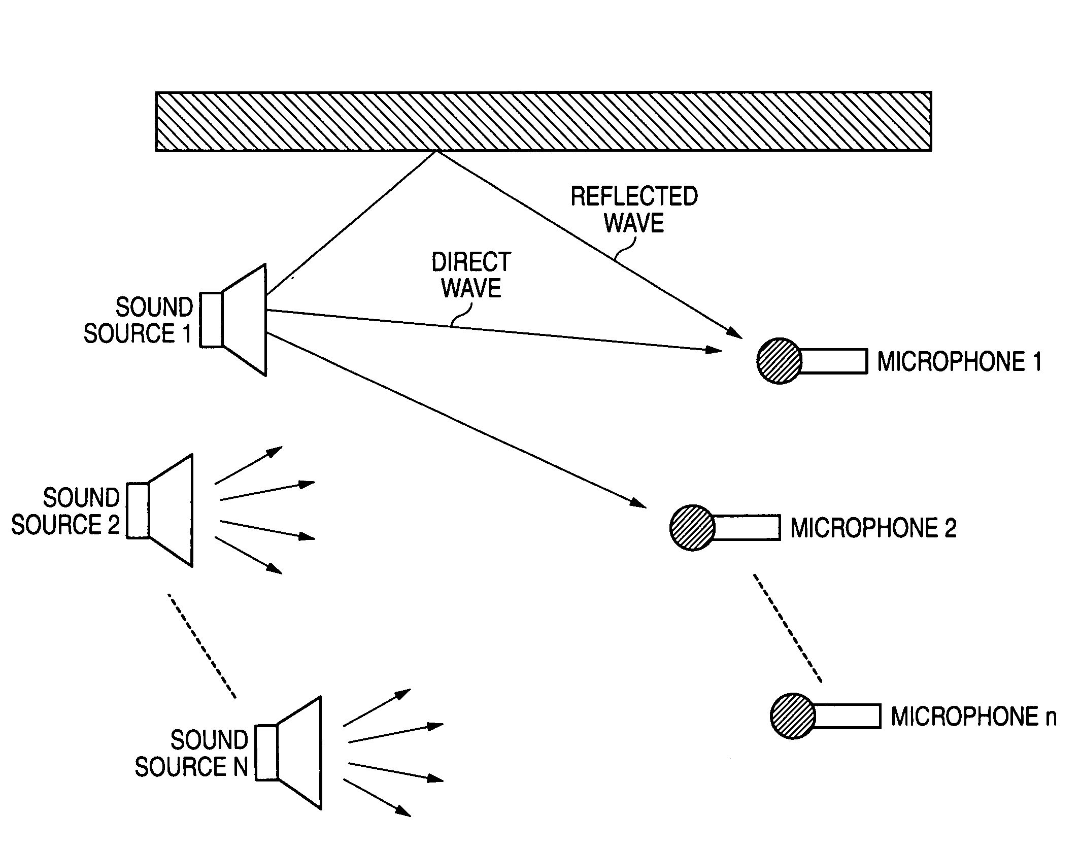
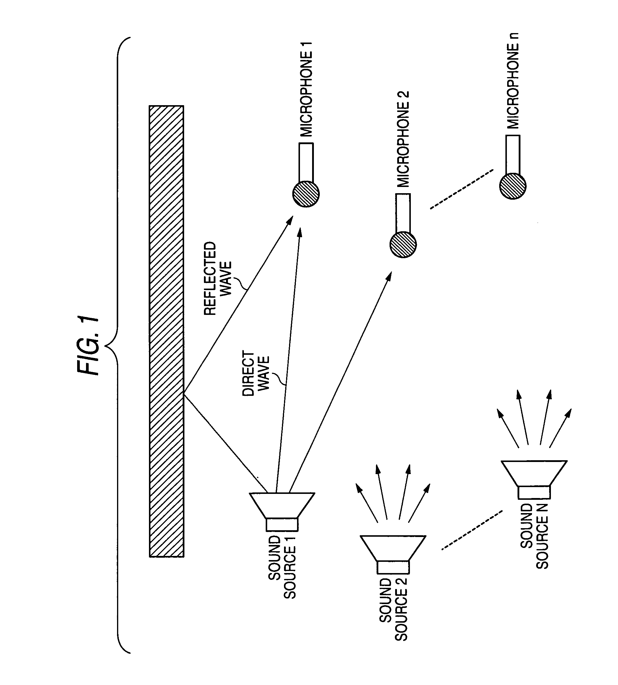
[0172]Specifically, as shown in FIG. 5, different sounds are emitted from N sound sources 111-1 to 111-N and the sounds are observed with n microphones 121-1 to 121-n. In such a situation, the signal separation processing by the independent component analysis (ICA) is performed on the basis of mixed signals acquired with the microphones 121-1 to 121-n.

[0173]As explained above, signals observed by one microphone j...


PUM


Abstract

A signal separating device that is inputted with signals formed by mixing plural signals and separates the signals into individual signals includes a signal converting unit that converts input signals into signals in the time-frequency domain and generates observation spectrograms and a signal separating unit that generates separated results from the observation spectrograms generated by the signal converting unit. The signal separating unit interprets the observation spectrograms as observation signals subjected to convolutive mixtures in the time-frequency domain and generates separated results by executing processing for solving convolutive mixtures in the time-frequency domain.

Description

CROSS-REFERENCES TO RELATED APPLICATIONS[0001]The present invention contains subject matter related to Japanese Patent Applications JP 2007-041455 and JP 2007-328516 filed in the Japanese Patent Office on Feb. 21, 2007 and Dec. 20, 2007, respectively, the entire contents of which being incorporated herein by reference.BACKGROUND OF THE INVENTION[0002]1. Field of the Invention[0003]The present invention relates to a signal separating device, a signal separating method, and a computer program, and, more particularly to a signal separating device, a signal separating method, and a computer program for separating a signal formed by mixing plural signals into the respective signals using an independent component analysis (ICA).[0004]2. Description of the Related Art[0005]A method of an independent component analysis (ICA) for separating and restoring, when plural original signals are linearly mixed with unknown coefficients, the original signals using only statistical independence attrac...

Claims


Application Information

Patent Timeline
IPC IPC(8): G10L11/00G10L21/00
CPCG10L21/0272G10L25/27G10L25/18
Inventor HIROE, ATSUO
Owner SONY CORP
Why Eureka
Try Eureka