Rainwater "real time" flow indicator and debris collection device for gutter downspout

a technology of gutter downspout and flow indicator, which is applied in the direction of roof covering, roofs, constructions, etc., can solve the problems of water entering the gutter, etc., and water entering the siding

Inactive Publication Date: 2008-09-25
LAMORTE JOSEPH +1
View PDF11 Cites 37 Cited by
  • Summary
  • Abstract
  • Description
  • Claims
  • Application Information

AI Technical Summary

Benefits of technology

[0051]The illustrative embodiments of the present inventive device provide for the “real time” monitoring of the flow of rainwater therethrough and through the gutter system; the speedy, almost automatic evaluation and ascertainment of the water transporting properties of the gutter system; and the frequent cleaning and maintenance thereof before a blockage in the gutter system gets aggravated to the point that the gutter system overflows. It comprises an enclosure having an inlet, an outlet, means for monitoring the flow of rainwater through the enclosure, a debris collecting screen inserted into and mounted within said enclosure, a first adaptor and a second adaptor, both adaptors configured and dimensioned to integrally connect the enclosure to a gutter downspout and a rubber joint designed to provide mechanical support for and allow movement of the enclosure relative to at least one of the adaptors.

Problems solved by technology

Debris accumulation is particularly problematic in gutters under a valley in the roof (e.g., where two differing slopes intersect) because the valleys tend to collect debris and drain it into the gutter below the valley, at a much higher rate.
When the debris accumulates in the guttering system to the point that the guttering system can no longer adequately drain and direct the water away from the roof and away from the building, the water will inevitably overflow in and start to pour over the edge of the horizontal gutters and run down the sides of the building.
This can cause a number of serious problems.
For example, if a building has siding, the water can seep behind the siding, and leak into the building.
If such seepage is coupled with a severe drop in the outside temperature, i.e., the weather gets so cold that the water freezes, it can cause the siding to break up and or separate from the house.
Failure to replace the siding will cause further damage to the building.
It may even increase the building owner's liability due to tailing siding.
The replacement of the siding of a building is a large and expensive job which will either require an investment of a tremendous amount of time or the hiring of a carpenter or contractor.
The water can find its way into all the minute cracks and crevices, freeze with the drop of the outside temperature and expand, thereby causing the side of the building to break up.
Consequently even with stucco or brick, water spilling over from the guttering system will physically erode that surface at a much higher rate than it would if the water is properly diverted.
This in turn may compromise the building by leading to cracks in the building's basement walls, and / or the building's foundation, and seeping into the lower part of the building itself.
Or alternatively, the water will not seep into the ground, but will stay on the surface where it can freeze and cover the whole area with a sheet of ice thereby making it very treacherous to walk anywhere in the immediate vicinity of the building.
Or even still, water may start to accumulate and become trapped on certain sections of the roof.
This may wear the roof down and eventually lead to a leak in the roof causing damage to the sections of the house protected by the roof.
Nothing provides for an advance notice or warning that debris has started to accumulated and beginning to block the flow of rainwater, or of an impending overflow.
It does so with either complex, multi-component apparatus that is costly difficult to install, and not user-friendly; or with cuplike, concave debris collecting screen structures, or solid receptacles, that can be accessed either through doors, apertures, or openings in the side walls of the devices themselves, or through the complete disassembly thereof.
Thus, generally speaking and on the most part, the only time that the users of the devices in the prior art will think of removing the debris is when the blockage actually occurs (this time from the very debris that has accumulated in the devices themselves), the rainwater backs tip, overflows over the edges of the horizontal sections of the gutter system along the eaves of the roof, and spills and gushes all over the side walls of the buildings.
Repeated blockages of this sort, will cause the very problems that the prior art has been designed to avoid.
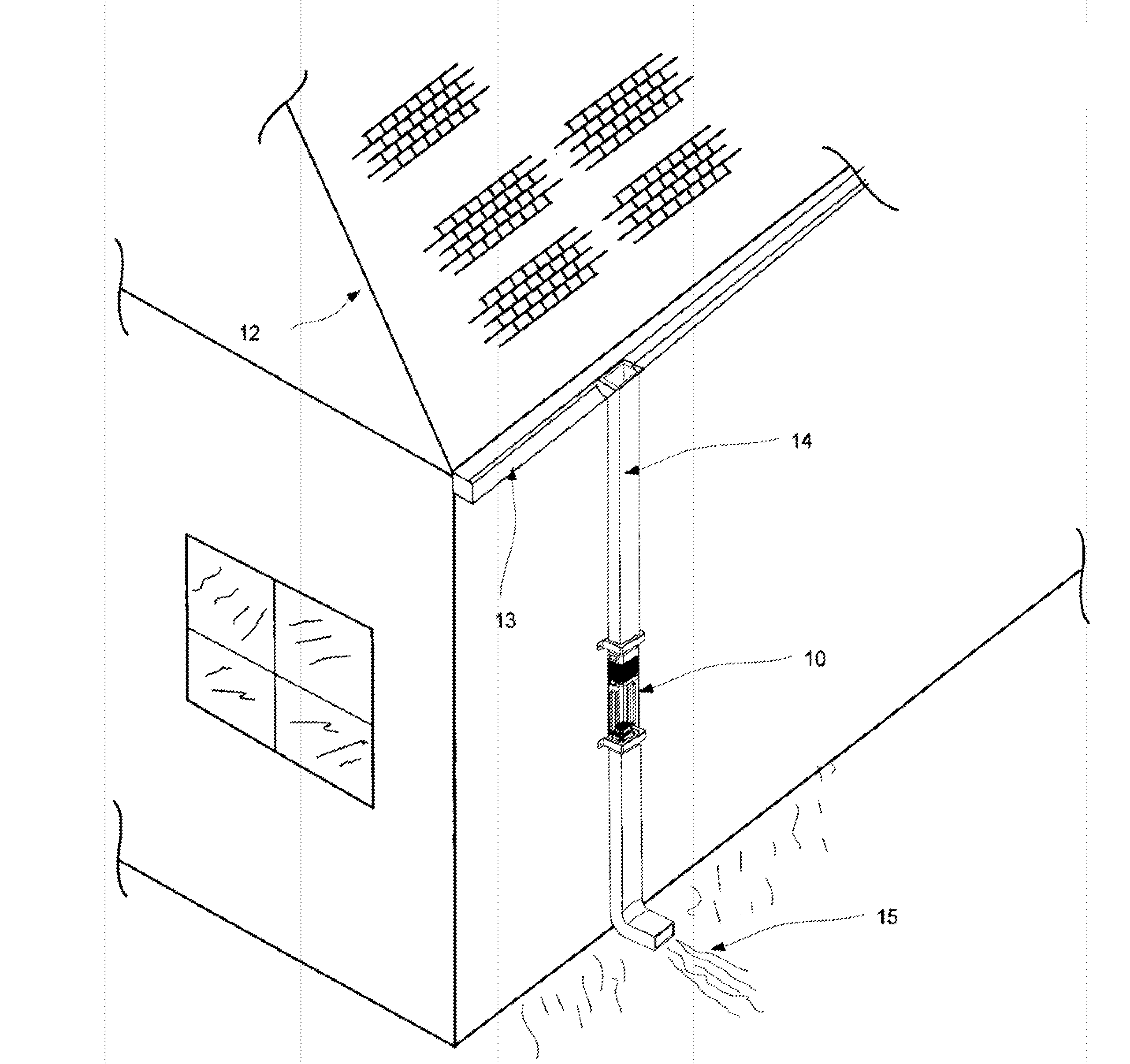
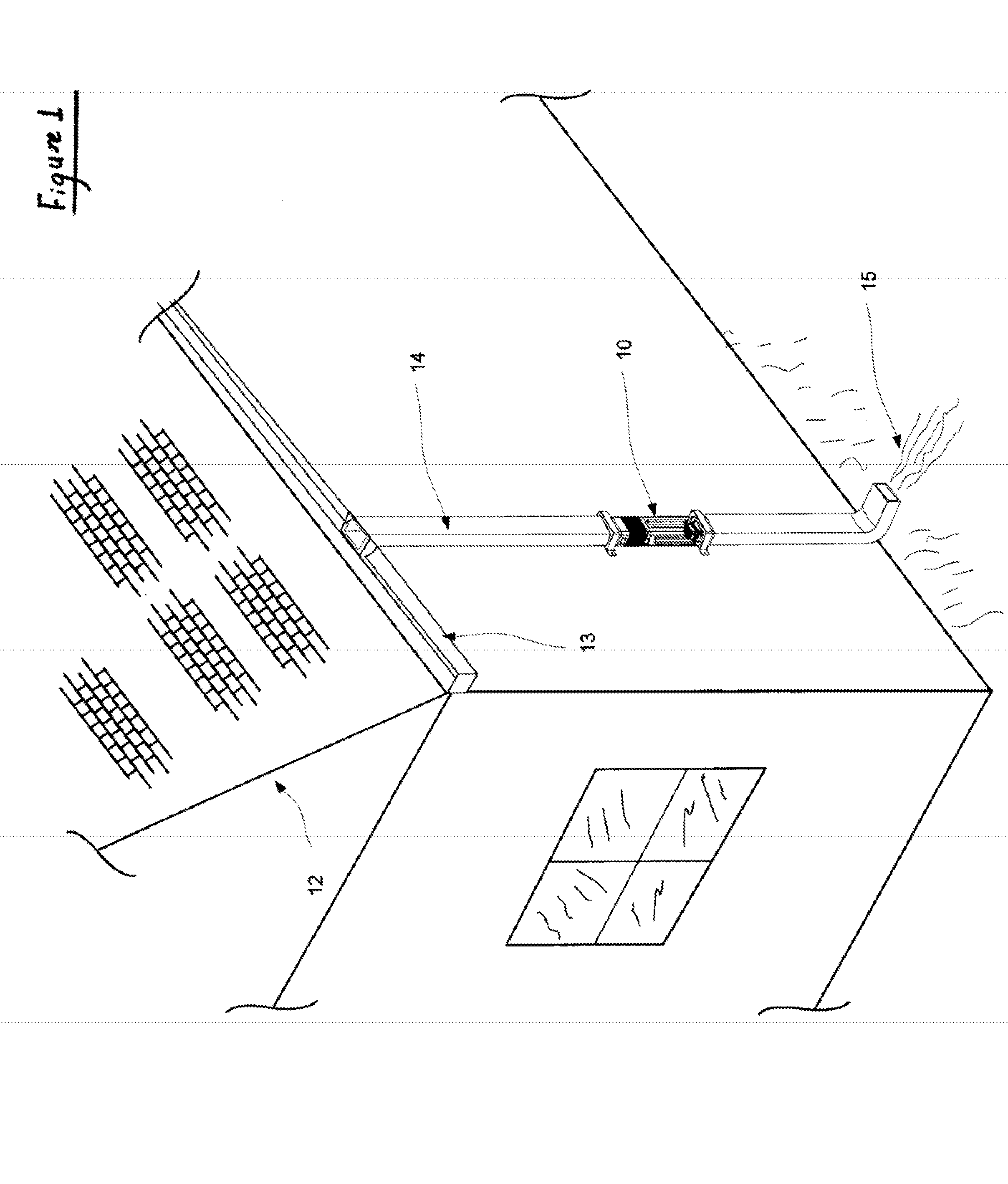
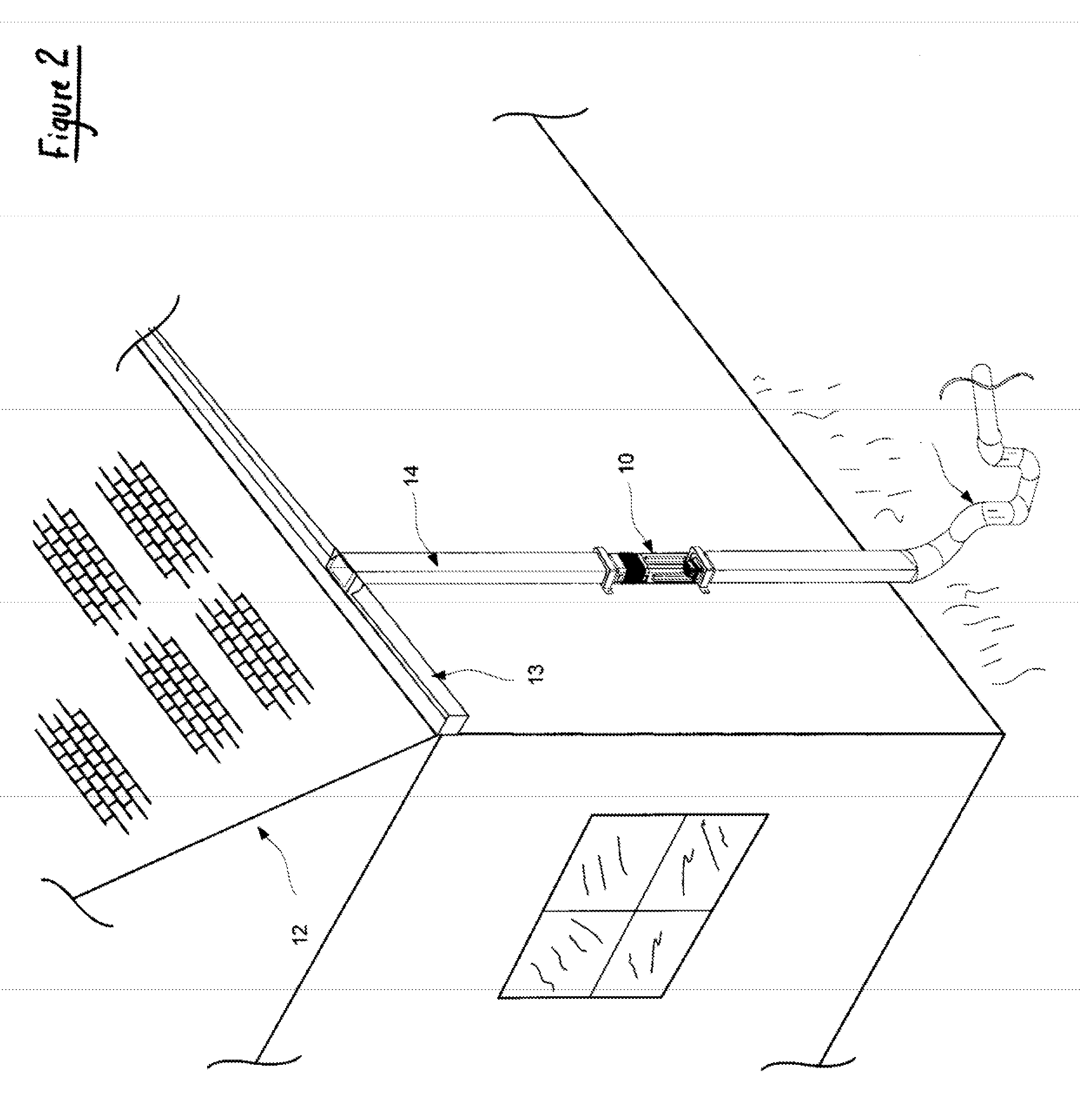
None of the prior art provides for a solution to the situation that arises if debris accumulates and clogs a section of the rainwater gutter system that is not accessible, as for example when debris is trapped in the upper section of the downspout, close to the roof, high above ground level.

Method used


Image

  • Rainwater "real time" flow indicator and debris collection device for gutter downspout
  • Rainwater "real time" flow indicator and debris collection device for gutter downspout
  • Rainwater "real time" flow indicator and debris collection device for gutter downspout

Examples


Embodiment Construction

[0116]Referring more specifically to the drawings, FIG. 1 and FIG. 2 generally depict the inventive device, The Rain Water Flow Indicator and Debris Collection Device for a Gutter Downspout (hereinafter “the Device”) at 10. It is designed to provide: (i) “real time” monitoring of the flow of rain water through said Device 10, as it courses through the rain water gutter system (hereinafter “the Gutter System”): (ii) early detection of a blockage and advanced warning that the flow of water through the Gutter System has been obstructed, before the Gutter System overflows; (iii) a window of opportunity to remove from the Gutter System, any debris that might be causing or that might cause a blockage, before the Gutter System overflows; (iv) for the removal of debris from rain water as it flows through the downspout 14 and away from the building; and (v) for the installation and use of the Device 10, without great cost or tremendous expertise, irrespective of whether the Gutter System is ...


PUM


Abstract

A rainwater flow indicator and debris collection device designed for integral installation in a gutter downspout. It comprises an enclosure that has means for monitoring the flow of rainwater through the enclosure; a debris collecting screen which is inserted into and mounted within the rainwater flow indicator and debris collection device; a first adaptor and a second adaptor, both of the adaptors configured and dimensioned to integrally connect the enclosure to the gutter downspout; and a rubber joint designed to provide mechanical support for and allow movement, of the enclosure relative to at least one of the adaptors.

Description

BACKGROUND OF THE INVENTION[0001]1. Field of the Invention[0002]The present invention relates generally to a method and apparatus for use in conjunction with gutter systems used for the collection of rainwater running off buildings' roofs and clean and efficient diversion of the rainwater therefrom. More particularly, the invention relates to debris collection devices that are integrally inserted in gutter downspouts to both remove debris carried by water flowing through the gutter system and to monitor the flow of rainwater runoff through the gutter system, for the purpose of readily detecting, predicting and receiving advanced warning of a potential blockage in the flow of rainwater runoff.[0003]2. Description of the Prior Art[0004]Buildings are generally equipped with rainwater gutter systems. These rainwater gutter systems typically comprise horizontal gutter segments, i.e., U-shaped troughs open at their uppermost end, running along the edge or cave of the roof of the buildings...

Claims


Application Information

Patent Timeline
Patent Type & Authority Applications(United States)
IPC IPC(8): E04D13/00
CPCE04D2013/086E04D13/08
Inventor LAMORTE, JOSEPHBORDONARO, JAMES JOSEPH
Owner LAMORTE JOSEPH
Why Eureka
Try Eureka