Flow Control

a compressor and flow control technology, applied in the direction of machines/engines, liquid fuel engines, lighting and heating apparatus, etc., can solve problems such as preventing or affecting compressor operation

Active Publication Date: 2008-09-25
LENOVO PC INT
View PDF4 Cites 0 Cited by
  • Summary
  • Abstract
  • Description
  • Claims
  • Application Information

AI Technical Summary

Benefits of technology

[0003]The present invention contemplates that the problems of prior compressor structures relying upon conventional check valves may be obviated by using, instead, flow control passages which operate to control flow while avoiding mechanical moving elements which may become problematical. In realizing this purpose of the invention, reliance is placed upon specifically configured flow passages, which dynamically direct fluid flow to achieve the desired functionality.

Problems solved by technology

Such check valves, while long used in such applications and well known, have known mechanical failures, including sticking or becoming unseated, which impair or prevent compressor operation.

Method used


Image

  • Flow Control
  • Flow Control
  • Flow Control

Examples


Embodiment Construction

[0011]While the present invention will be described more fully hereinafter with reference to the accompanying drawings, in which a preferred embodiment of the present invention is shown, it is to be understood at the outset of the description which follows that persons of skill in the appropriate arts may modify the invention here described while still achieving the favorable results of the invention. Accordingly, the description which follows is to be understood as being a broad, teaching disclosure directed to persons of skill in the appropriate arts, and not as limiting upon the present invention.

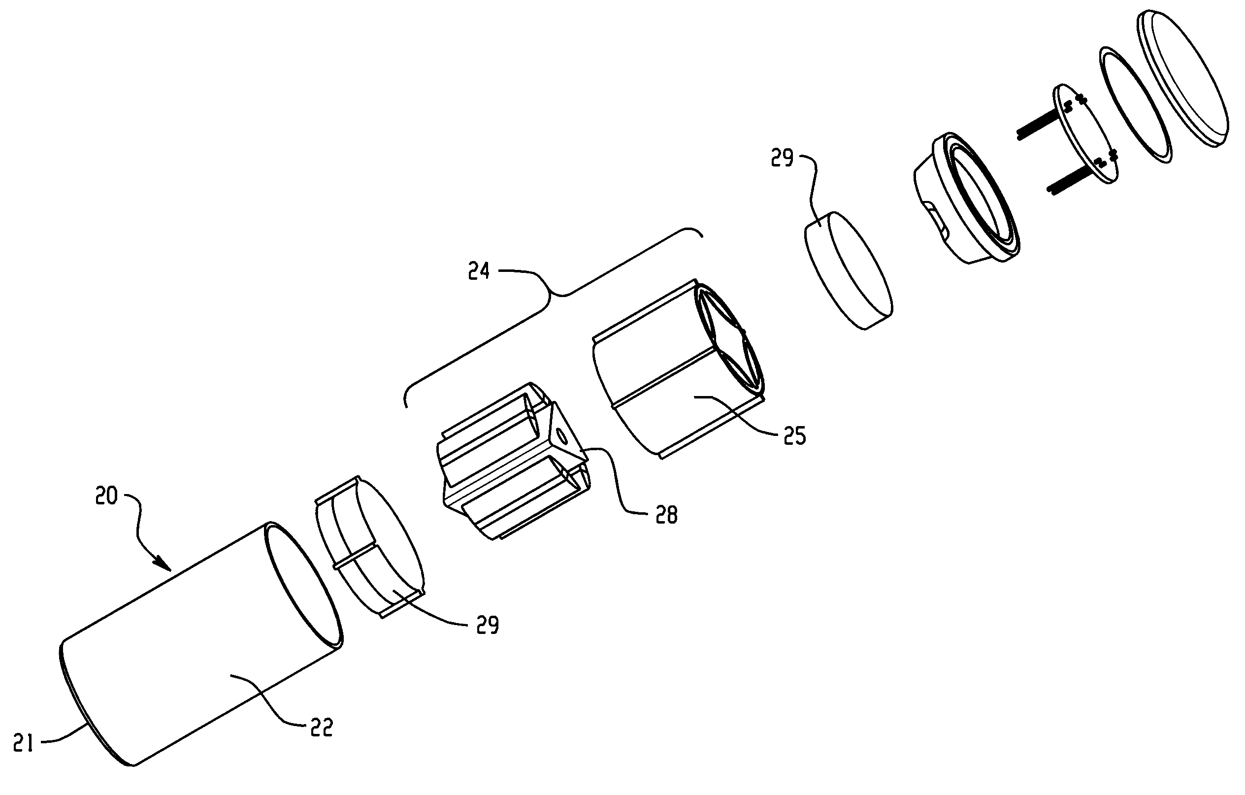
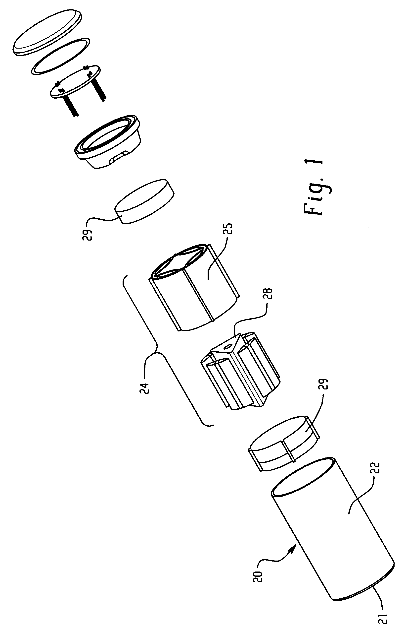
[0012]FIG. 1 shows an exploded assembly view of an apparatus which includes a compressor stage in accordance with this invention. The apparatus illustrated is an electro mechanical refrigeration device, operating on the Carnot cycle of expansion or evaporation of a fluid to absorb heat, compression of the expanded fluid, and condensation of the compressed fluid to transfer the absorbed h...


PUM


Abstract

The problems of prior compressor structures relying upon conventional check valves are obviated by using, instead, flow control passages which operate to control flow while avoiding mechanical moving elements which may become problematical.

Description

FIELD AND BACKGROUND OF INVENTION[0001]This invention relates to flow control in a compressor and more particularly to arrangements which obviate the need for more conventional check valves.[0002]The has been a proposal to use a trilobal impeller or rotor within a quadrilateral housing to move a fluid, such as a refrigerant fluid, from a region of low pressure to a region of higher pressure, in a manner consistent with the operation or prior art compressors. In such devices, conventional check valves, formed with spring loaded balls seated on seats, have been used to control flow through the compressor. Such check valves, while long used in such applications and well known, have known mechanical failures, including sticking or becoming unseated, which impair or prevent compressor operation.SUMMARY OF THE INVENTION[0003]The present invention contemplates that the problems of prior compressor structures relying upon conventional check valves may be obviated by using, instead, flow con...

Claims


Application Information

Patent Timeline
Patent Type & Authority Applications(United States)
IPC IPC(8): F25B41/06
CPCF04C18/10F25B3/00F04C29/12Y10T137/7837
Inventor FARROW, TIMOTHY SAMUELMAKLEY, ALBERT VINCENT
Owner LENOVO PC INT
Why Eureka
Try Eureka