Motor-Driven Power Steering Apparatus

a technology of motor drive and power steering, which is applied in the direction of field or armature current control, non-deflectable wheel steering, underwater vessels, etc., can solve the problems of motor and a and the motor and the motor drive circuit being thermally damaged

a technology of motor drive and power steering, which is applied in the direction of field or armature current control, non-deflectable wheel steering, underwater vessels, etc., can solve the problems of motor and a and the motor and the motor drive circuit being thermally damaged

US20080230302A1Inactive Publication Date: 2008-09-25SHOWA CORP

Image

  • Motor-Driven Power Steering Apparatus
  • Motor-Driven Power Steering Apparatus
  • Motor-Driven Power Steering Apparatus

Examples


Embodiment Construction

[0021]A description will be given below of an embodiment in accordance with the present invention with reference to FIGS. 1 to 11.

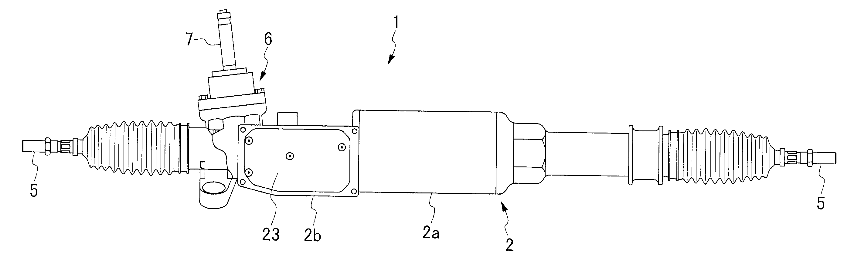
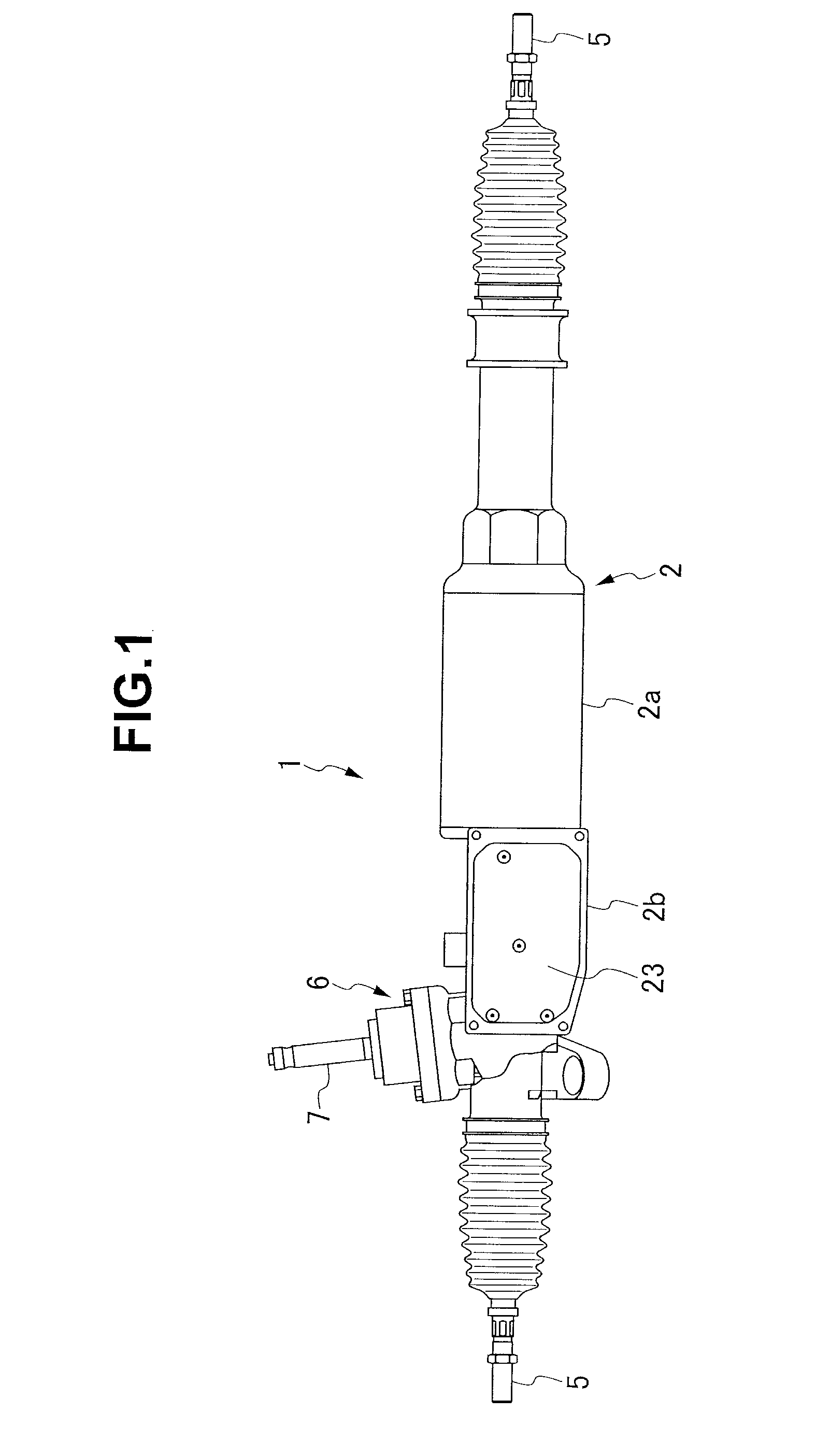
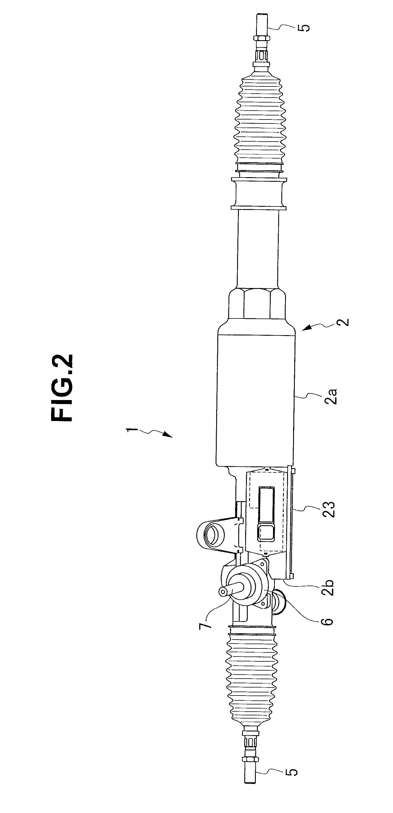
[0022]A front elevational view of a whole of a motor-driven power steering apparatus 1 in accordance with the present embodiment is shown in FIG. 1, a top elevational view is shown in FIG. 2, and a front elevational view showing an internal structure of the same is shown in FIG. 3.

[0023]The motor-driven power steering apparatus 1 is structured such that a rack shaft 3 is accommodated within an approximately cylindrical rack case 2 directed to a lateral direction (light and left sides are inversely shown in FIGS. 1, 2 and 3) of a vehicle so as to be slidable in a lateral axial direction.

[0024]The rods 5 and 5 are moved to both end portions of the rack shaft 3 protruding from openings in both ends of the rack case 2 respectively joints 4 and 4, and steered wheels of the vehicle are steered via a steering mechanism.

[0025]A steering gear box 6 is provided nea...


PUM


Abstract

The invention provides a motor-driven power steering apparatus provided with a fault diagnosing means diagnosing a fault of a board temperature detecting apparatus on the basis of an armature current Im detected by a motor current detecting means and a board temperature Tb of the control board detected by the board temperature detecting apparatus, and a target current suppressing means suppressing a target current Iq at a time when the fault diagnosing means diagnoses that the board temperature detecting apparatus is out of order

Description

BACKGROUND OF THE INVENTION[0001]1. Field of the Invention[0002]The present invention relates to a motor-driven power steering apparatus, and more particularly relates to fault diagnosis of a temperature sensor of the motor-driven power steering apparatus used for temperature compensation of a drive motor or the like.[0003]2. Description of the Related Art[0004]In a motor-driven power steering apparatus used as a drive source assisting a steering operation, since the motor-driven power steering apparatus is arranged within an engine room in which an internal combustion engine is arranged and a heat is generated, and the motor itself generates heat, a temperature of the motor is widely variable.[0005]Particularly, if the temperature of the motor is increased so as to become equal to or higher than a predetermined temperature, there is a risk that the motor and a motor drive circuit may be thermally damaged. Accordingly, there has been proposed an example (for example, refer to Japane...

Claims


Application Information

Patent Timeline
25 Sep 2008
Publication
US20080230302A1
IPC
B62D5/04; G06F19/00; B62D6/00; B62D107/00; B62D119/00; B62D137/00; H02P7/29
CPC
B62D5/0463; B62D5/0496; B62D5/049; B62D5/0484
Inventors
TAMAKI, AKIHIRO