
Heat block

Inactive Publication Date: 2008-09-25
ORIENT SEMICON ELECTRONICS
View PDF11 Cites 2 Cited by
  • Summary
  • Abstract
  • Description
  • Claims
  • Application Information

AI Technical Summary

Benefits of technology

[0008]Therefore, an aspect of the present invention is to provide a heat block to discharge electricity when holding an electronic device, thereby preventing the electronic device from being burned out by unexpected current or charge.
[0012]Therefore, with the application of the heat block disclosed in the embodiments of the present invention, the heat block discharges electricity when holding the electronic device, so as to prevent the electronic device form being burned out by unexpected current or charge. Further, when the discharge device of the heat block is in contact with the electronic device, the discharge device can prevent the electronic device from damage, such as scrape damage.

Problems solved by technology

Therefore, the chip can be burned out by the discharge, and could be unusable.

Method used


Image

  • Heat block
  • Heat block
  • Heat block

Examples


Embodiment Construction

[0021]In order to make the illustration of the present invention more explicit and complete, the following description is stated with reference to FIG. 1 through FIG. 7.

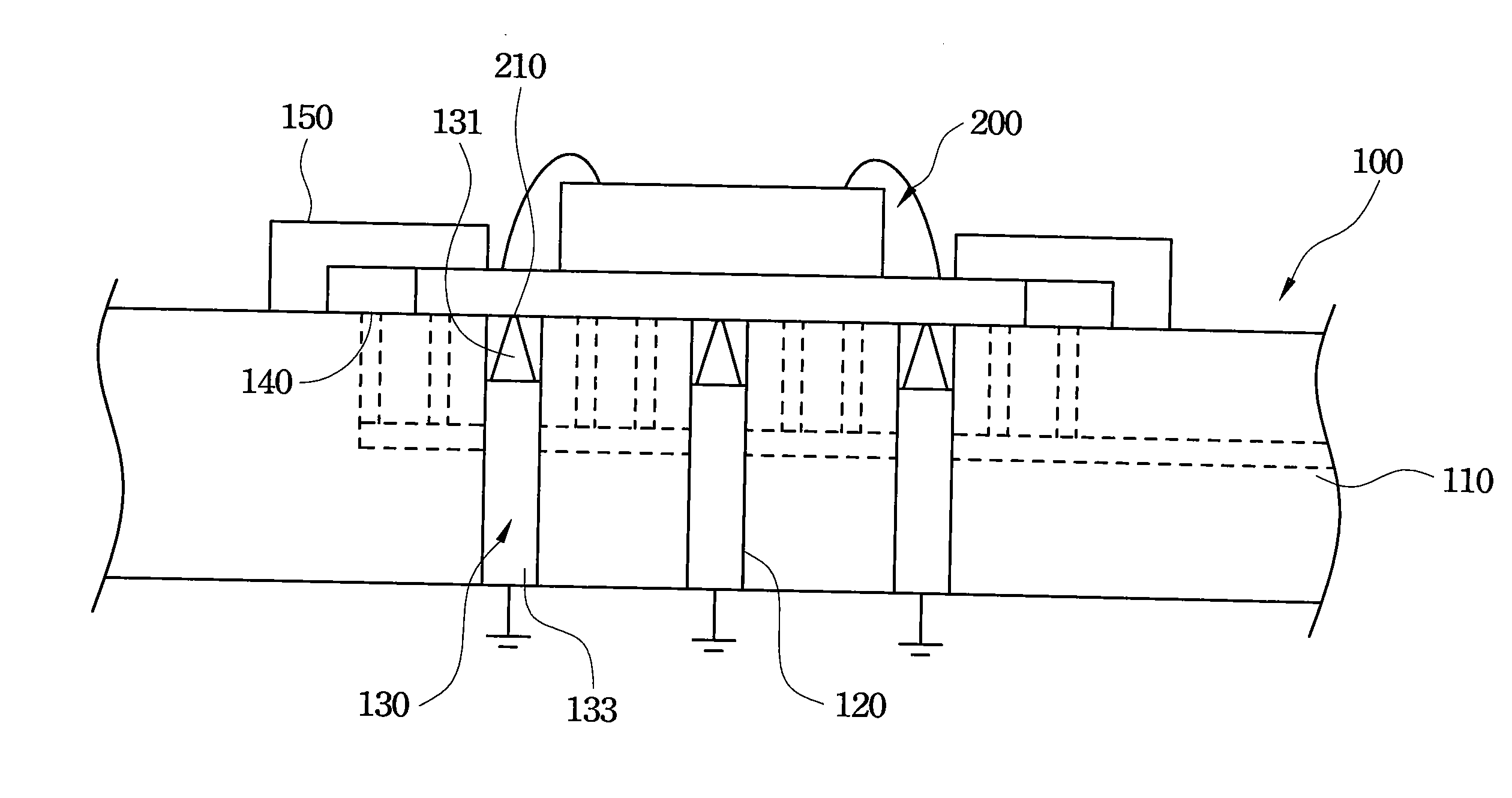
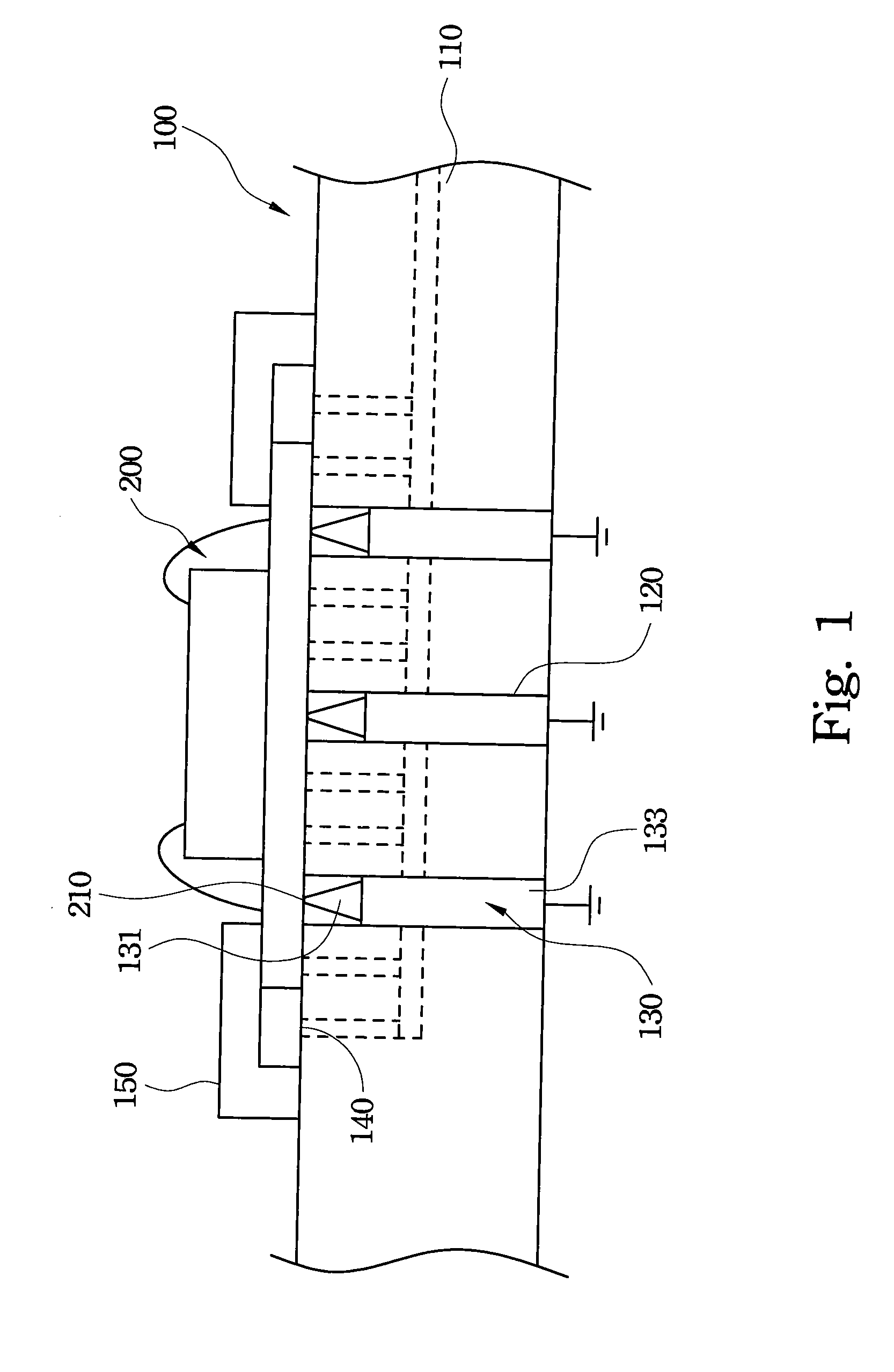
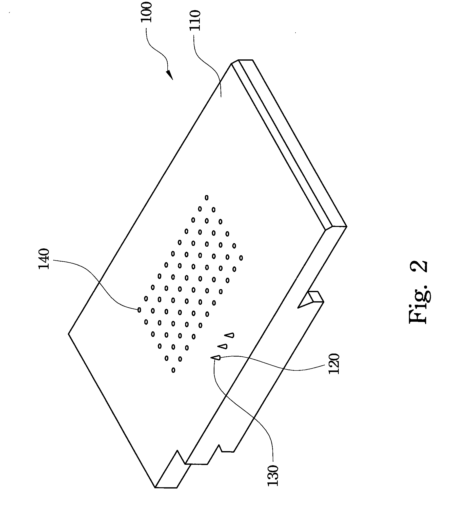
[0022]Refer to FIG. 1 and FIG. 2. FIG. 1 is a cross-sectional view showing a heat block according to a first embodiment of the present invention, and FIG. 2 is a three dimensional view of a heat block according to a first embodiment of the present invention. The heat block 100 of the first embodiment is disposed on a wire bonding equipment to hold an electronic device (not shown). The electronic device 200 may be a holder bonding with a chip and / or a passive device, and the holder may be a lead frame, a substrate, a printed circuit board or a flexible circuit board. However, the electronic device 200 may be other electronic devices but not limited to the above description. The heat block 100 comprises a base 110, at least one receiving hole 120, at least one discharge device 130 and at least one vacuum attracting hol...


PUM


Abstract

A heat block for holding an electronic device is disclosed. The heat block comprises a base and at least one discharge device. The discharge device is disposed on the base. The discharge device is electrically conductive and is grounded. When the electronic device is placed on the base, the discharge device is in contact with an electrical contact of the electronic device.

Description

RELATED APPLICATIONS[0001]This application claims priority to Taiwan Application Serial Number 96109602, filed Mar. 20, 2007, which is herein incorporated by reference.BACKGROUND OF THE INVENTION[0002]1. Field of the Invention[0003]This invention relates to a heat block, and more particularly, to a heat block that discharges electricity when holding an electronic device.[0004]2. Description of the Related Art[0005]In the semiconductor package process, the chip is disposed on a holder, such as a lead frame or a flexible circuit board. Then, a wire bonding process is performed, and a conducting wire (gold wire) is respectively connected to the chip and the holder, thereby electrically connecting the chip and the holder.[0006]When the wire bonding process is performed, the holder bonding with the chip is first placed on a heat block of the wire bonding equipment, and then a hold down clamp holds the chip to stabilize the chip on the heat block for wire bonding. Meanwhile, the heat bloc...

Claims


Application Information

Patent Timeline
IPC IPC(8): H05B3/20
CPCH01L24/45H01L2924/01033H01L2224/45144H01L2224/48091H01L2224/7825H01L2224/78703H01L2224/85H01L2924/01047H01L2924/01079H01L2924/01082H05B3/22H05K9/0067H01L24/85H01L2924/00014H01L24/48H01L2224/78744H01L23/34H01L23/36
Inventor CHOU, CHIH-MINGWANG, YU-JENWANG, CHAO-YUNGLIN, YU-PINGSU, CHEN-PING
Owner ORIENT SEMICON ELECTRONICS
Learn More