Suction cup and suction cup device

a technology of suction cups and suction cups, which is applied in the direction of shaving accessories, other domestic objects, machine supports, etc., can solve the problems of increasing size, and achieve the effects of increasing the retentivity of shape, increasing the thickness thereof, and increasing the scale of the shap

Inactive Publication Date: 2008-09-25
SONY CORP
View PDF4 Cites 46 Cited by
  • Summary
  • Abstract
  • Description
  • Claims
  • Application Information

AI Technical Summary

Benefits of technology

[0013]According to an embodiment of the present invention, there is provided a suction cup comprising a suction cup body formed from gel and having at least one flat or convex face serving as a suction face, a shape retaining member provided on the suction cup body and having elasticity for restoring, when the suction cup body is deformed, the suction cup body so as to restore an original shape thereof, and a center stem connected to the suction cup body and projecting from a portion of the suction cup body positioned remotely from a location of the suction cup body at which the suction face is provided in a direction intersecting with the center of the suction face.
[0014]According to another embodiment of the present invention, there is provided a suction cup device comprising a suction cup, an attaching base, and a displacement mechanism, the suction cup including a suction cup body formed from gel and having at least one flat or convex face serving as a suction face, a shape retaining member provided on the suction cup body and having elasticity for restoring, when the suction cup body is deformed, the suction cup body so as to restore an original shape thereof, and a center stem connected to the suction cup body and projecting from a back face of the suction cup body positioned remotely from a location of the suction cup body at which the suction face is provided in a direction intersecting with the center of the suction face, the attaching base having an attaching portion to which an article is to be attached, and a contacting portion capable of contacting with an outer circumferential portion of the back face of the suction cup body or with an attaching object face to which the suction face is attracted on the outer side with respect to the back face, the displacement mechanism being provided between the attaching base and the center stem in such a manner as to displace the center stem in a direction away from the suction face in a state wherein the suction face contacts closely with the attaching object face and the contracting portion contacts with the outer circumferential portion of the back face of the suction cup body or with the attaching object face to which the suction face is attracted on the outer side with respect to the back face.
[0015]With the suction cup and the suction cup device, since the portion of the suction cup including the suction face is formed from gel, not only where the attaching object face is formed as a flat face, but also where the attaching object face is formed as a leather-emboss face or as a fine uneven face or else as a rough face, the suction face deforms following up the convex and concave configuration. Consequently, the suction face can be closely attached to the uneven face or rough face without the intervention of a gap between the suction face and the uneven face. This is advantageous where it is tried to attach various articles with certainty to the attaching object face such as a leather-emboss face of a dashboard panel or the like.
[0016]Further, since the suction cup is not configured such that a gel layer made of gel is stacked on a suction cup body made of rubber but is configured such that the entire suction cup body including the suction face is formed from gel while the shape retaining member is provided simultaneously on the suction cup body to raise the retentivity of the shape of the suction cup body, the suction cup can be formed without increasing the thickness thereof, that is, without increasing the scale thereof. This is advantageous where it is tried to achieve miniaturization of the suction cup 22.

Problems solved by technology

On the other hand, since the gel does not have elasticity and the gel itself cannot maintain its shape, in the suction cup which uses the gel layer described above, the gel layer is attached to an attaching face of the suction cup formed from rubber or the like.
Therefore, the suction cup has a thickness equal to the sum of the thickness of the gel layer and the thickness of a conventional suction cup and is disadvantageous in that it has an increased size.

Method used


Image

  • Suction cup and suction cup device
  • Suction cup and suction cup device
  • Suction cup and suction cup device

Examples


first embodiment

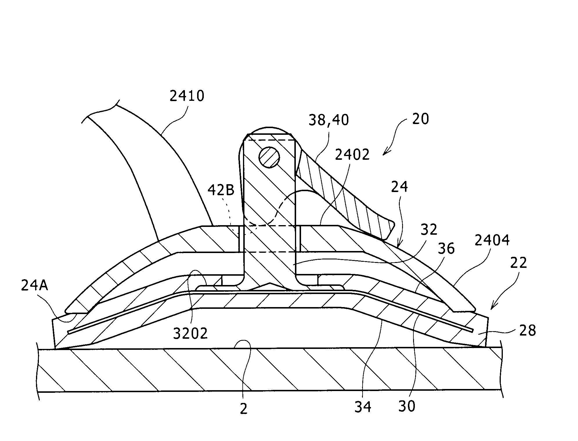
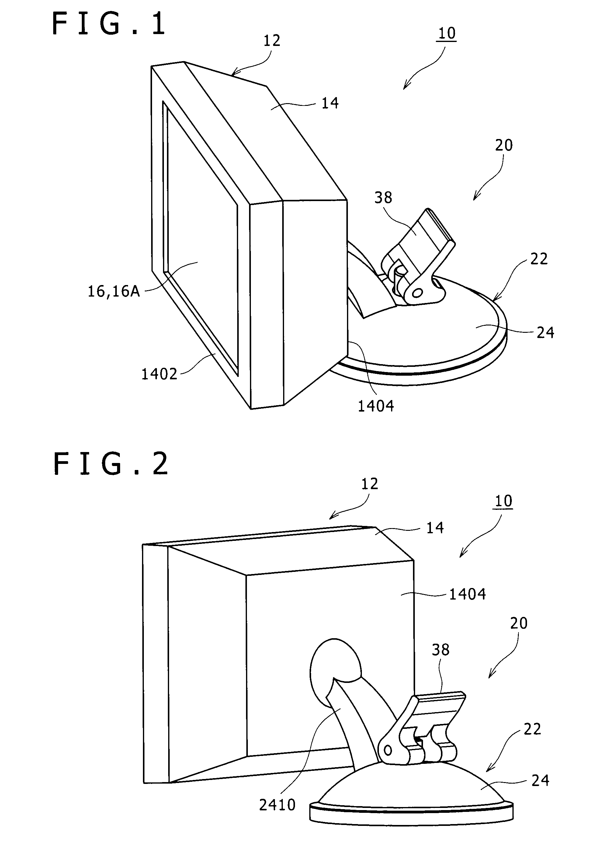
[0037]Referring first to FIGS. 1 to 6, there is shown an electronic apparatus which includes an electronic apparatus 10 according to a first embodiment of the present invention is incorporated.

[0038]The electronic apparatus 10 includes an apparatus body 12 and a suction cup device 20 according to the present invention.

[0039]The apparatus body 12 is a display panel, for example, of a car navigation system or a television apparatus disposed on a dashboard within a cabin or a windshield of an automobile.

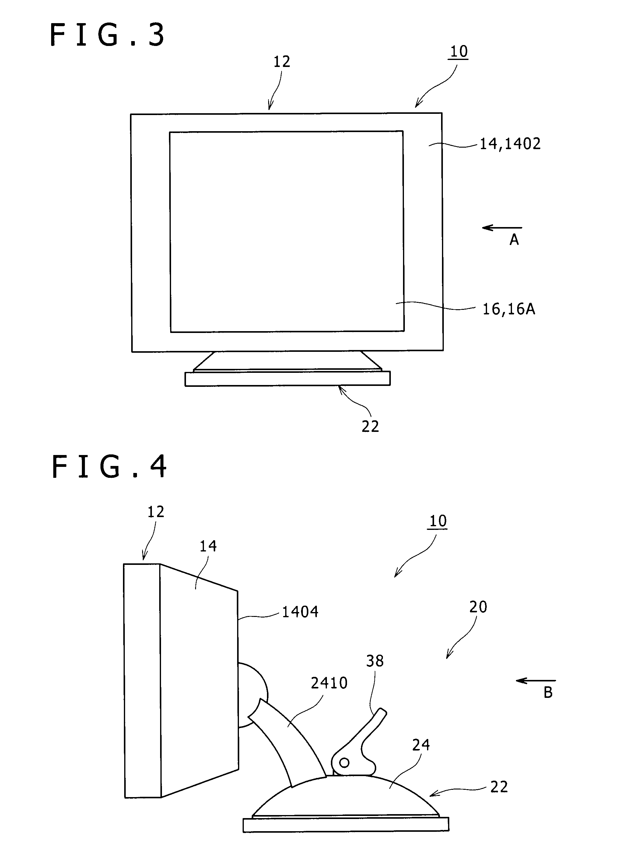
[0040]The apparatus body 12 includes a housing 14 in the form of a rectangular plate, and a display apparatus 16.

[0041]The display apparatus 16 is formed from a in the past known display apparatus such as a liquid crystal display apparatus or an organic EL display apparatus, and has a display screen 16A for displaying an image thereon.

[0042]The display screen 16A is incorporated in the housing 14 such that it is exposed forwardly through an opening provided on a front face 1402 of the h...

second embodiment

[0073]FIG. 13A shows a shape retaining member 30 according to a second embodiment of the present invention, and FIG. 13B shows a suction cup 22 in which the shape retaining member 30 is incorporated.

[0074]It is to be noted that the shape retaining member 30 according to the second and other embodiments of the present invention described below is incorporated in the suction cup 22 which is incorporated in the suction cup device 20 and hence in the electronic device 10 described hereinabove with reference to FIGS. 1 to 6 similarly to the shape retaining member 30 according to the first embodiment of the present invention. Therefore, in the description of the second and other embodiments of the present invention, description is given principally of the shape retaining member 30.

[0075]Referring to FIGS. 13A and 13B, the shape retaining member 30 according to the second embodiment is formed such that a bar-like member 44 having elasticity which may be formed from a thin wire member or a ...

third embodiment

[0078]FIG. 14A shows a shape retaining member 30 according to a third embodiment of the present invention, and FIG. 14B shows a suction cup 22 in which the shape retaining member 30 is incorporated.

[0079]Referring to FIGS. 14A and 14B, the shape retaining member 30 according to the third embodiment includes a plurality of annular members 46 and a plurality of connecting members 48.

[0080]The annular members 46 are each formed from a thin wire member or a thin plate member having elasticity and are disposed concentrically on the axis of the suction face 34. The annular members 46 have different diameters from each other.

[0081]The connecting members 48 are provided at locations spaced from each other in a circumferential direction of the suction cup body 28, extend radially from a central portion of the suction face 34 toward the outer circumference of the suction cup body 28 and connect the annular members 46.

[0082]Each of the connecting members 48 has a cutaway portion 48A at which i...


PUM


Abstract

Disclosed herein is a suction cup, including: a suction cup body formed from gel and having at least one flat or convex face serving as a suction face; a shape retaining member provided on the suction cup body and having elasticity for restoring, when the suction cup body is deformed, the suction cup body so as to restore an original shape; and a center stem connected to the suction cup body and projecting from a portion of the suction cup body positioned remotely from a location of the suction cup body at which the suction face is provided in a direction intersecting with the center of the suction face.

Description

CROSS REFERENCES TO RELATED APPLICATIONS[0001]The present invention contains subject matter related to Japanese Patent Application JP 2007-072505 filed in the Japan Patent Office on Mar. 20, 2007, the entire contents of which being incorporated herein by reference.BACKGROUND OF THE INVENTION[0002]1. Field of the Invention[0003]This invention relates to a suction cup and a suction cup device.[0004]2. Description of the Related Art[0005]A suction cup is in the past known which is used to attach an article to a wall face indoors or a dashboard of an automobile.[0006]In the past, a suction cup of the type mentioned is formed as a disk made of rubber or the like, and one of faces thereof in the thicknesswise direction serves as a suction face for attracting an attaching object face while the other face thereof serves as the back face.[0007]The suction cup is attracted to an attaching object face if a central portion is pressed down toward the attaching object face with the suction face t...

Claims


Application Information

Patent Timeline
Patent Type & Authority Applications(United States)
IPC IPC(8): F16B47/00
CPCF16B47/006
Inventor TAKAHASHI, SHUNICHIKAWABATA, MAKOTO
Owner SONY CORP
Why Eureka
Try Eureka