Liquid crystal display device

a liquid crystal display and display device technology, applied in the manufacture of electrode systems, electric discharge tubes/lamps, instruments, etc., can solve the problems of delay in lighting, complete disappearance of electroderons in tubes, etc., and achieve the effect of minimizing light leakag

Active Publication Date: 2008-09-25
LG DISPLAY CO LTD
View PDF8 Cites 15 Cited by
  • Summary
  • Abstract
  • Description
  • Claims
  • Application Information

AI Technical Summary

Benefits of technology

[0016]Another advantage of the present invention is to provide a liquid crystal display device that can minimize light leakage by disposing an auxiliary optical source at a lower direction side of a fluorescent lamp.
[0017]To achieve these and other advantages and in accordance with the purpose of the present invention, as embodied and broadly described herein, there is provided a backlight unit, including: an optical source for irradiating light to a liquid crystal panel, wherein the optical source includes at least one fluorescent lamp for supplying light to the liquid crystal panel, and at least one auxiliary optical source for supplying light to the fluorescent lamps.
[0018]There is further provided a bottom cover disposed below the liquid crystal panel to receive the fluorescent lamps and having at least one through-holes; and a reflector disposed above the bottom cover, covering the through-holes and reflecting the light emitted from the fluorescent lamps toward the liquid crystal panel.
[0019]To achieve these and other advantages and in accordance with the purpose of the present invention, there is provided a liquid crystal display device, including: a liquid crystal panel; at least one fluorescent lamps disposed below the liquid crystal panel and supplying light to the liquid crystal panel; a bottom cover disposed below the liquid crystal panel to receive the fluorescent lamps and having at least one through-holes; an inverter board disposed below the bottom cover and having an inverter to apply a voltage to the fluorescent lamps; and one or more auxiliary optical sources mounted on the inverter board and supplying light to the fluorescent lamps through the through-holes of the bottom cover.
[0020]The foregoing and other features, aspects and advantages of the present invention will become more apparent from the following detailed description of the present invention when taken in conjunction with the accompanying drawings.

Problems solved by technology

However, if the fluorescent lamp is kept in darkness for a long time, the electrons in the tube completely disappear.
Thus, a time during which a current does not flow in the tube continues, causing a delay in lighting.
Such time delay in lighting may cause a problem of displaying an image in the liquid crystal display device when the liquid crystal display device is left alone in the darkness for a long time.

Method used


Image

  • Liquid crystal display device
  • Liquid crystal display device
  • Liquid crystal display device

Examples


Embodiment Construction

[0026]Reference will now be made in detail to an embodiment of the present invention, example of which is illustrated in the accompanying drawings.

[0027]Hereinafter, a liquid crystal display device according to the present invention will be explained in detail with reference to the accompanying drawings.

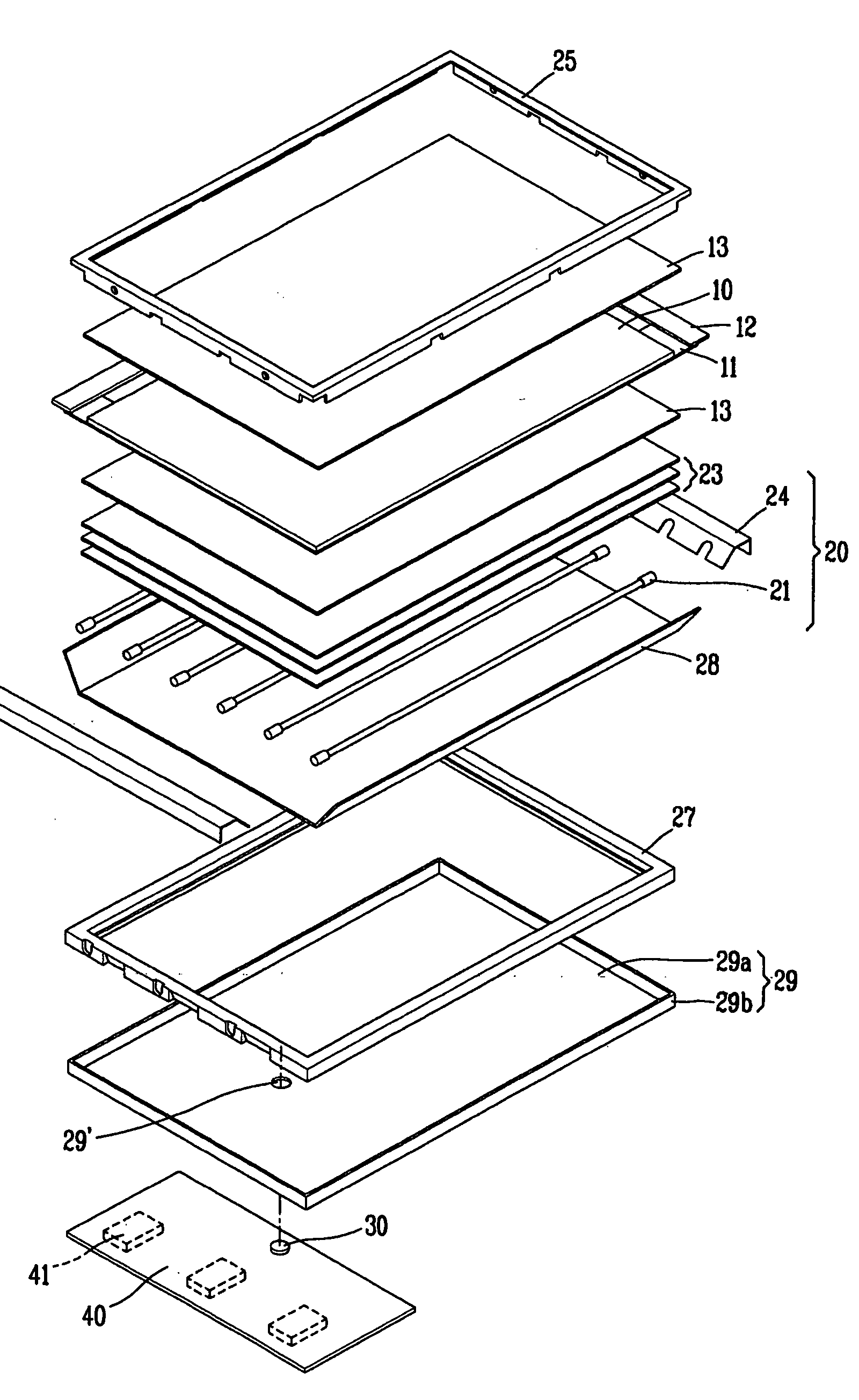
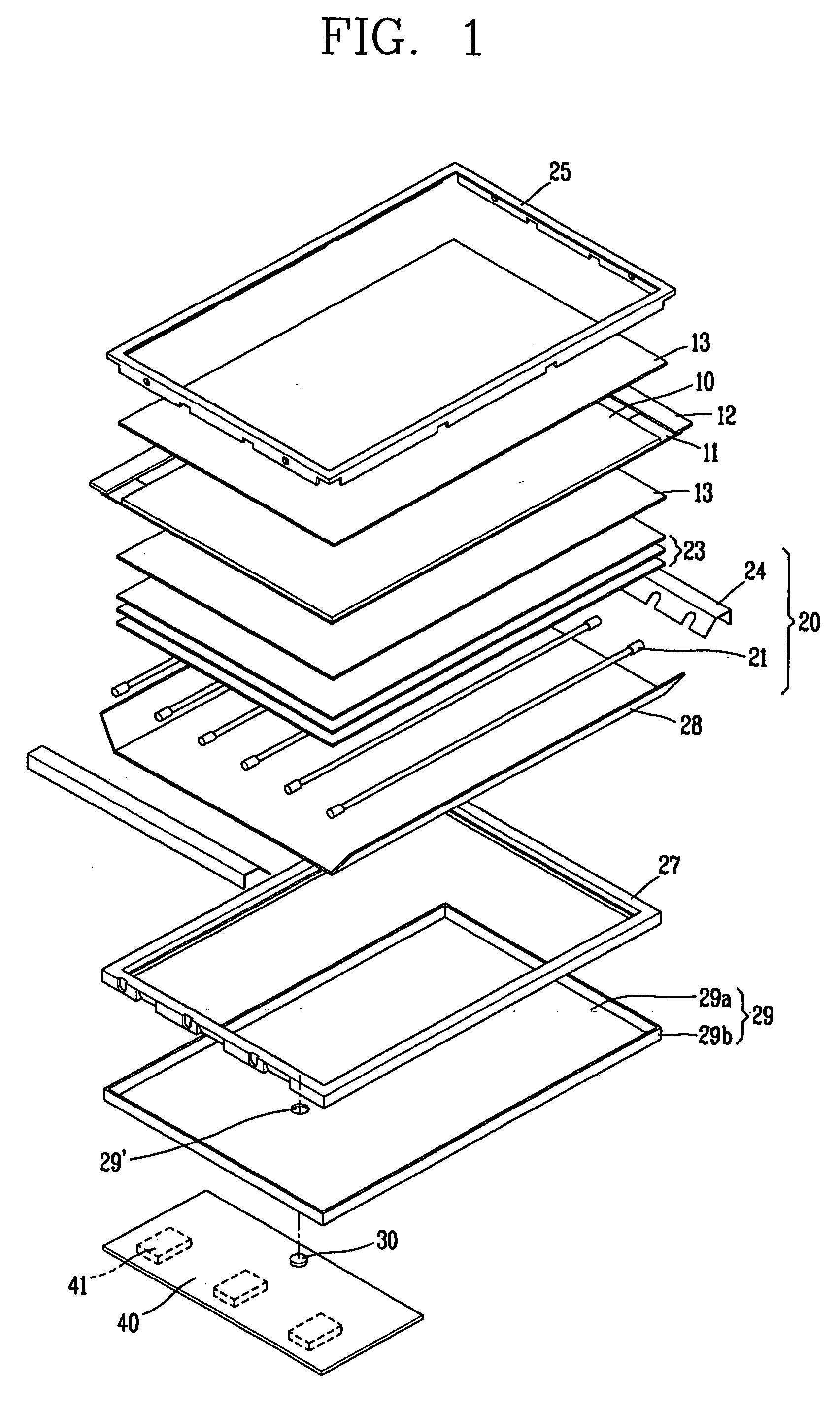
[0028]FIG. 1 is an exploded perspective view showing a liquid crystal display device according to one embodiment of the present invention, and FIG. 2 is a cross-sectional view showing a liquid crystal display device according to one embodiment of the present invention.

[0029]Referring to FIGS. 1 and 2, the liquid crystal display device according to the present invention includes a liquid crystal panel 10 for displaying an image, a backlight unit 20 for supplying light from behind or below the liquid crystal panel 10, a main frame 27 for supporting an edge portion of the liquid crystal panel 10, a bottom cover 29 disposed behind or below the backlight unit 20 and housing or mounting th...


PUM

PropertyMeasurementUnit
wavelengthaaaaaaaaaa

Abstract

A liquid crystal display device capable of reducing a time delay in lighting of the liquid crystal display device includes a liquid crystal panel, at least one fluorescent lamps disposed below the liquid crystal panel, formed as a cylindrical shape having a central axis and supplying light to the liquid crystal panel, and at least one auxiliary optical source disposed to face the liquid crystal panel while having the central axis therebetween and supplying light to the fluorescent lamps.

Description

[0001]This application claims the benefit of Korea Patent Application No. 10-2007-0028263, filed on Mar. 22, 2007, which is hereby incorporated by reference for all purposes as if fully set forth herein.BACKGROUND OF THE INVENTION[0002]1. Field of the Invention[0003]The present invention relates to a liquid crystal display device, and more particularly, to a liquid crystal display device capable of reducing a time delay in lighting.[0004]2. Discussion of the Related Art[0005]With the rapid development in various fields of electronic devices, such as mobile phones, PDAs (Personal Digital Assistants), computers and large-screen TVs, the need for a flat panel display device applicable to such devices has recently been increased.[0006]Flat panel display devices, such as an LCD (Liquid Crystal Display), a PDP (Plasma Display Panel), an FED (Field Emission Display), a VFD (Vacuum Fluorescent Display) and the like have been actively studied. However, considering the technology for mass pro...

Claims


Application Information

Patent Timeline
Patent Type & Authority Applications(United States)
IPC IPC(8): G02F1/1333G02F1/13357
CPCG02F1/133604G02F1/133603G02F1/1333G02F1/1335
Inventor LEE, YOUNG-EUN
Owner LG DISPLAY CO LTD
Why Eureka
Try Eureka