Thin polarizing plate and method of manufacturing the same

a polarizing plate and thin technology, applied in the field of thin polarizing plates, can solve the problems of reducing limiting the reduction of the thickness of the polarizer, and increasing the swelling of the pva-based film, so as to achieve the effect of improving the productivity of manufacturing the polarizing plate, reducing the curvature, and superior optical properties

Active Publication Date: 2018-08-14
SHANJIN OPTOELECTRONICS (NANJING) CO LTD
View PDF39 Cites 0 Cited by
  • Summary
  • Abstract
  • Description
  • Claims
  • Application Information

AI Technical Summary

Benefits of technology

[0015]In a method of manufacturing a thin polarizing plate according to exemplary embodiments of the present disclosure, a thin polarizing plate having superior optical properties may be manufactured. In a case in which a polyvinyl alcohol (PVA)-based film is attached to both surfaces of a base film, productivity in manufacturing the polarizing plate may be increased and various types of polarizing plate may be manufactured in a single process.
[0016]In addition, the thin polarizing plate manufactured using the method of manufacturing a thin polarizing plate according to exemplary embodiments of the present disclosure may be less curled, and thus, when such a thin polarizing plate is applied to a display device, light leakage may be minimized.

Problems solved by technology

In a case in which the thickness of the PVA-based film is equal to or less than 60 μm prior to the stretching process, the degree of swelling in the PVA-based film may be increased, and a modulus of such a thin film per unit area may be increased during the stretching process, whereby breakage of the film may easily occur.
However, in the case in which a PVA-based film having a thickness exceeding 60 μm is used according to the related art, there has been a limitation on reducing the thickness of a polarizer.
However, in the case of using the coating or co-extruding method, the PVA layer and the base layer may not easily be separated from each other after stretching.
Since a high degree of peel strength is required for the separation therebetween, defects such as damage to or a deformation of the PVA layer may occur during the separation process, resulting in a deterioration of optical properties of the PVA-based film, such as the degree of polarization and the like.
Thus, the physical properties of the resultant PVA film may deteriorate and uniformity thereof may not be obtained.

Method used


Image

  • Thin polarizing plate and method of manufacturing the same
  • Thin polarizing plate and method of manufacturing the same
  • Thin polarizing plate and method of manufacturing the same

Examples


##ventive example 1

Inventive Example 1

[0094]A thin film polarizer manufacturing test was performed by forming a film laminate by attaching PVA films to both surfaces of a thermoplastic polyurethane base film of 60 μm using attractive force therebetween, and stretching the film laminate through wet stretching. Here, the PVA film was a PVA film of 30 μm (M3000 grade manufactured by Nippon Synthetic Chemical Industry Co., Ltd.). After the PVA films were subjected to a swelling process in a pure water solution at 25° C. for 15 seconds, they were dyed in a solution having an iodine concentration of 0.3 wt % at 25° C. for 60 seconds. Then, after the PVA films were subjected to a cleaning process in a solution having a boric acid concentration of 1 wt % at 25° C. for 15 seconds, they were stretched at a magnification of 7 times in a solution having a boric acid concentration of 2.5 wt % at 52° C. After the stretching process, the PVA films were subjected to a complementing process in a solution having a KI c...

experimental example 1

[0099]Single transmittance (Ts), cross transmittance (Tc), degree of polarization (DOP), single color (a, b), and cross color (a, b) of the thin polarizing plates manufactured according to Inventive Example 1 and Comparative Example 2 were measured using a JASCO V-7100 Spectrophotometer.

[0100]

TABLE 1Single ColorCross ColorTs(%)Tc(%)DOP(%)ababInventive42.550.064799.8275−0.032.052.40−1.41ExampleComparative34.970.125999.4971−0.070.562.12−3.01Example 2

[0101]According to Table 1, although the Inventive Example had higher single transmittance (Ts) than that of Comparative Example 2, it exhibited the degree of polarization (DOP) higher than that of Comparative Example 2. Therefore, it can be seen that the Inventive Example had superior optical performance to that of Comparative Example 2.

[0102]Meanwhile, in the case of manufacturing a thin film polarizer using a coating method under the same manufacturing process conditions as those of the Inventive Example as in Comparative Example 1, the...

experimental example 2

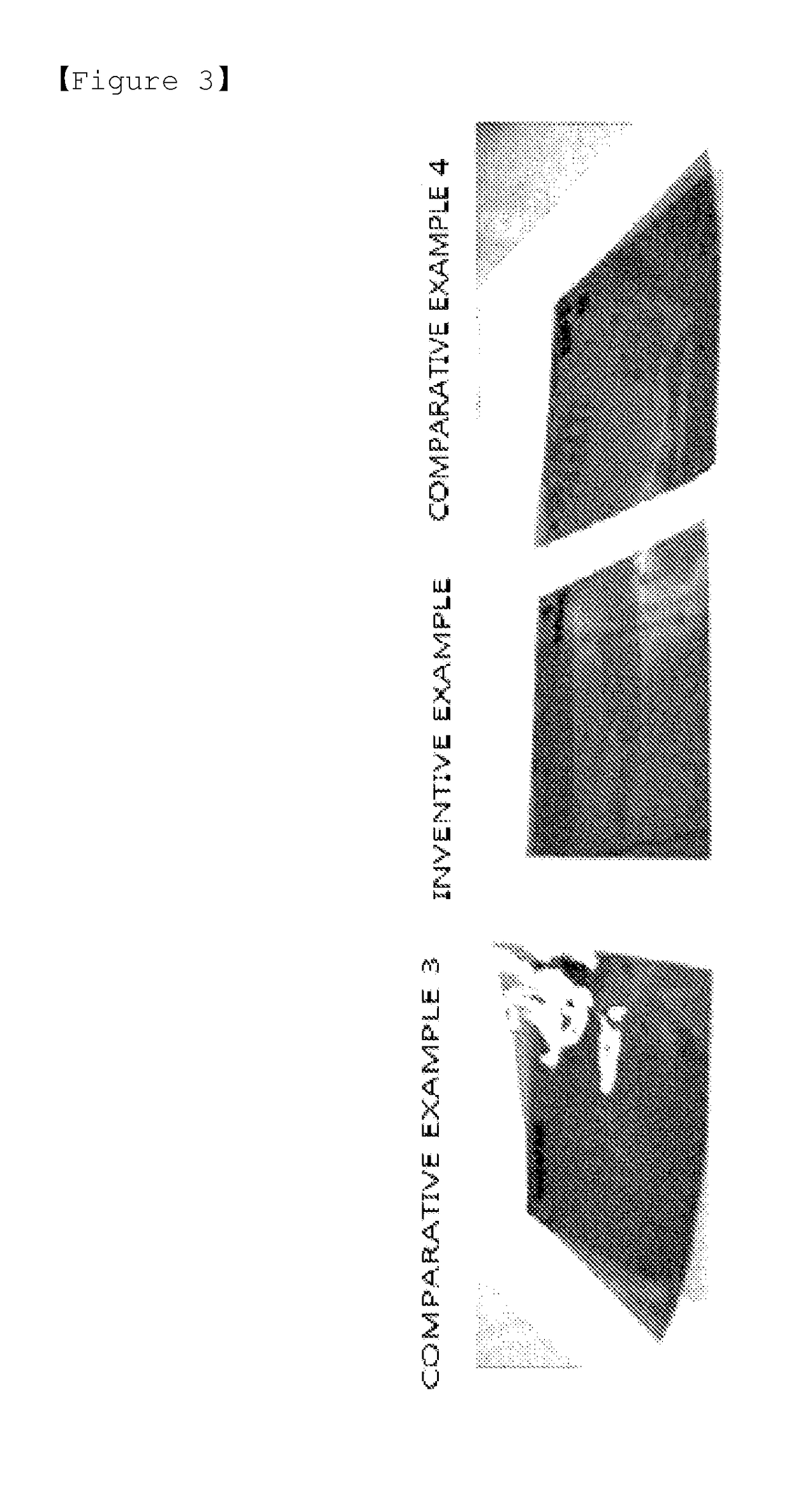
[0103]Curling properties of the polarizing plates manufactured according to the Inventive Example and Comparative Examples 3 and 4 were observed with the naked eye. Photographs of the corresponding polarizing plates are illustrated in FIG. 3. With reference to FIG. 3, it can be seen that the polarizing plate manufactured according to the Inventive Example had a lower degree of curling as compared with the polarizing plates manufactured according to Comparative Examples 3 and 4.

Experimental Example 3—Evaluating Uniformity in Degree of Polarization

[0104]With respect to the polarizers manufactured according to Inventive Example 1 and Comparative Example 2, the degrees of polarization were measured at 10 equidistant points on each polarizer in the width direction, and then a standard deviation in the measured degrees of polarization was calculated. The degrees of polarization were measured using a JASCO V-7100 Spectrophotometer. The measurement results are shown in Table 2.

[0105]

TABLE 2...


PUM

PropertyMeasurementUnit
temperatureaaaaaaaaaa
adhesive strengthaaaaaaaaaa

Abstract

There is provided a method of manufacturing a thin polarizing plate including: forming a film laminate by attaching a non-stretched polyvinyl alcohol (PVA)-based film to a non-stretched base film, using attractive force therebetween or using an adhesive; stretching the film laminate; attaching a first protective film to the PVA-based film of the stretched film laminate; and separating the PVA-based film having the first protective film attached thereto from the base film.

Description

[0001]This application is a National Stage application of PCT / KR2014 / 005188, filed on Jun. 13, 2014, which claims priority to Korean Patent Application Nos. 10-2013-0069635, filed on Jun. 18, 2013, and 10-2014-0067820 filed on Jun. 3, 2014, all of which are hereby incorporated by reference in their entirety.TECHNICAL FIELD[0002]The present disclosure relates to a thin polarizing plate and a method of manufacturing the same, and more particularly, to a thin polarizing plate including a polarizer having a thickness of 10 μm or less and a method of manufacturing the same allowing for various types of polarizing plate to be manufactured in a single process.BACKGROUND ART[0003]A polarizer used in a polarizing plate is an optical device for converting natural light or randomly polarized light into light polarized in a certain direction, and it has been widely used in display devices such as liquid crystal displays (LCDs) and organic light emitting diodes (OLEDs). As a polarizer commonly u...

Claims


Application Information

Patent Timeline
Patent Type & Authority Patents(United States)
IPC IPC(8): G02B1/14B32B27/08B32B27/30B32B7/12G02B5/30B32B27/40B32B27/36B32B27/32B32B37/00B32B37/18B32B38/10B32B38/00B32B37/12
CPCG02B5/305B32B27/08B32B27/306B32B27/308B32B27/32B32B27/36B32B27/40B32B37/025B32B37/18B32B37/187B32B38/0012B32B38/10G02B1/14B32B7/12B32B2551/00B32B2037/0092B32B2037/1253B32B2038/0028B32B2307/42B32B2309/02B32B2309/105B32B2310/0831B32B2331/04G02B5/3033
Inventor NAM, SUNG-HYUNRAH, KYUN-ILJUNG, JONG-HYUNYU, HYE-MIN
Owner SHANJIN OPTOELECTRONICS (NANJING) CO LTD
Why Eureka
Try Eureka