Optical film, image display device, and liquid-crystal display device

a liquid crystal display device and optical film technology, applied in non-linear optics, instruments, optics, etc., can solve the problems of birefringence induced by liquid crystal molecules in the vicinity of the substrate, difficulty in displaying perfect black, and inability to avoid light leakage, so as to minimize light leakage

Inactive Publication Date: 2008-11-25
FUJIFILM HLDG CORP +1
View PDF8 Cites 1 Cited by
  • Summary
  • Abstract
  • Description
  • Claims
  • Application Information

AI Technical Summary

Benefits of technology

[0007]The present invention has been conceived in view of the circumstances, and aims at providing an optical film capable of minimizing leakage of light attributable to a view angle and changes in tint, which arise in an image display device.
[0019]According to the present invention, there can be provided an optical film capable of minimizing leakage of light attributable to a view angle and changes in tint, which arise in an image display device.

Problems solved by technology

However, even when an attempt is made to display black in the TN mode, birefringence is induced by liquid crystal molecules in the vicinity of the substrates because of a driving characteristic of the liquid-crystal display device.
As a result, leakage of light arises, to thereby pose difficulty in displaying perfect black.
However, when the display surface is observed from a direction deviating from the direction of the normal, leakage of light, which cannot be avoided for reasons of the characteristic of the polarizing plate, arises in directions deviating from the direction of the optical axis of each of the polarizing plates between which the liquid-crystal cell is sandwiched.
Consequently, there arises a problem of the angle of view (hereinafter called a “view angle”) becoming narrow.
However, this optical film can suppress leakage of light attributable to the view angle, but encounters difficulty in suppressing occurrence of changes in tint ascribable to the view field.

Method used


Image

  • Optical film, image display device, and liquid-crystal display device
  • Optical film, image display device, and liquid-crystal display device
  • Optical film, image display device, and liquid-crystal display device

Examples


first example

(Protective Films 1a, 1b)

[0110]75 parts by weight of an alternating copolymer consisting of isobutene and N-methylmaleimide (a content of N-methylmaleimide is 50 mol %) and 25 parts by weight of styrene-acrylonitrile copolymer having a content of 28 parts by weight of acrylonitrile were dissolved into methylene chloride, whereby an aqueous solution having a content of 15 parts by weight of solid was obtained. This solution was spread over a polyethylene terephthalate film laid on a glass plate, and was left for 60 minutes at room temperature. Subsequently, the film was exfoliated. After having been dried at 100° C. for ten minutes, the film was further dried at 160° C. for thirty minutes, whereupon protective films 1a, 1b, each of which has a thickness of 100 μm, were obtained. In-phase retardation Re2 of each of the protective films 1a, 1c was 4 nm, and thicknesswise retardation Rth of the same was 4 nm.

(Polarizing Plate)

[0111]The protective films 1a, 1c were laminated on each surf...

second example

[0116]The protective film and the polarizing plate, which are the same as those used in the first example, were used.
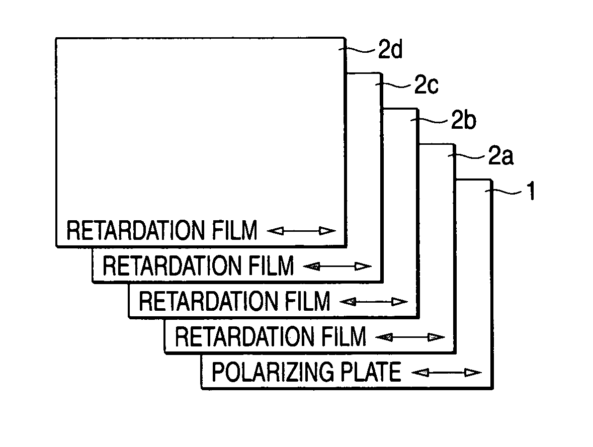
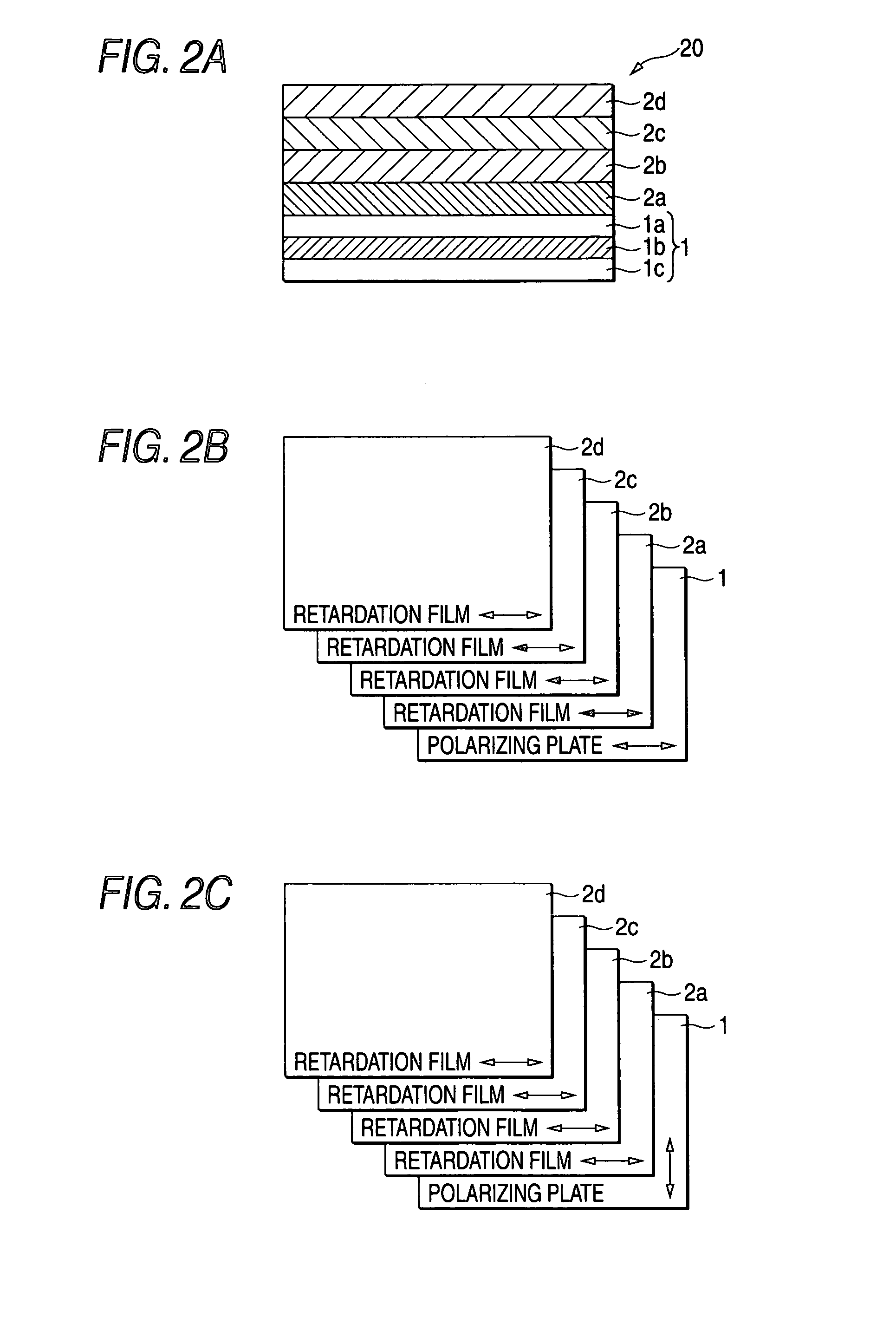
(Retardation Films)

[0117]The retardation films 2a, 2b, 2c, and 2d were prepared by means of stretching the polycarbonate film. The Nz value of the retardation film 2a was about 0.875; the Nz value of the retardation film 2b was about 0.625; the Nz value of the retardation film 2c was about 0.375; and the Nz value of the retardation film 2d was 0.125. The total of the Nz values was essentially 2. The in-plane retardation Re1 of each of the retardation films 2a, 2b, 2c, and 2d was 275 nm.

(Optical Film)

[0118]As shown in FIGS. 2B and 2C, the materials were laminated by use of the adhesive, to thus have prepared the two optical films 20.

(Liquid-Crystal Display Device)

[0119]By use of the thus-prepared two optical films 20, four liquid-crystal display devices, such as those shown in FIGS. 3 through 5 (each having a structure where the retardation film 2d is sandwiched betwee...

third example

[0121]The protective film and the polarizing plate, which are the same as those of the first example, were used.

(Retardation Films)

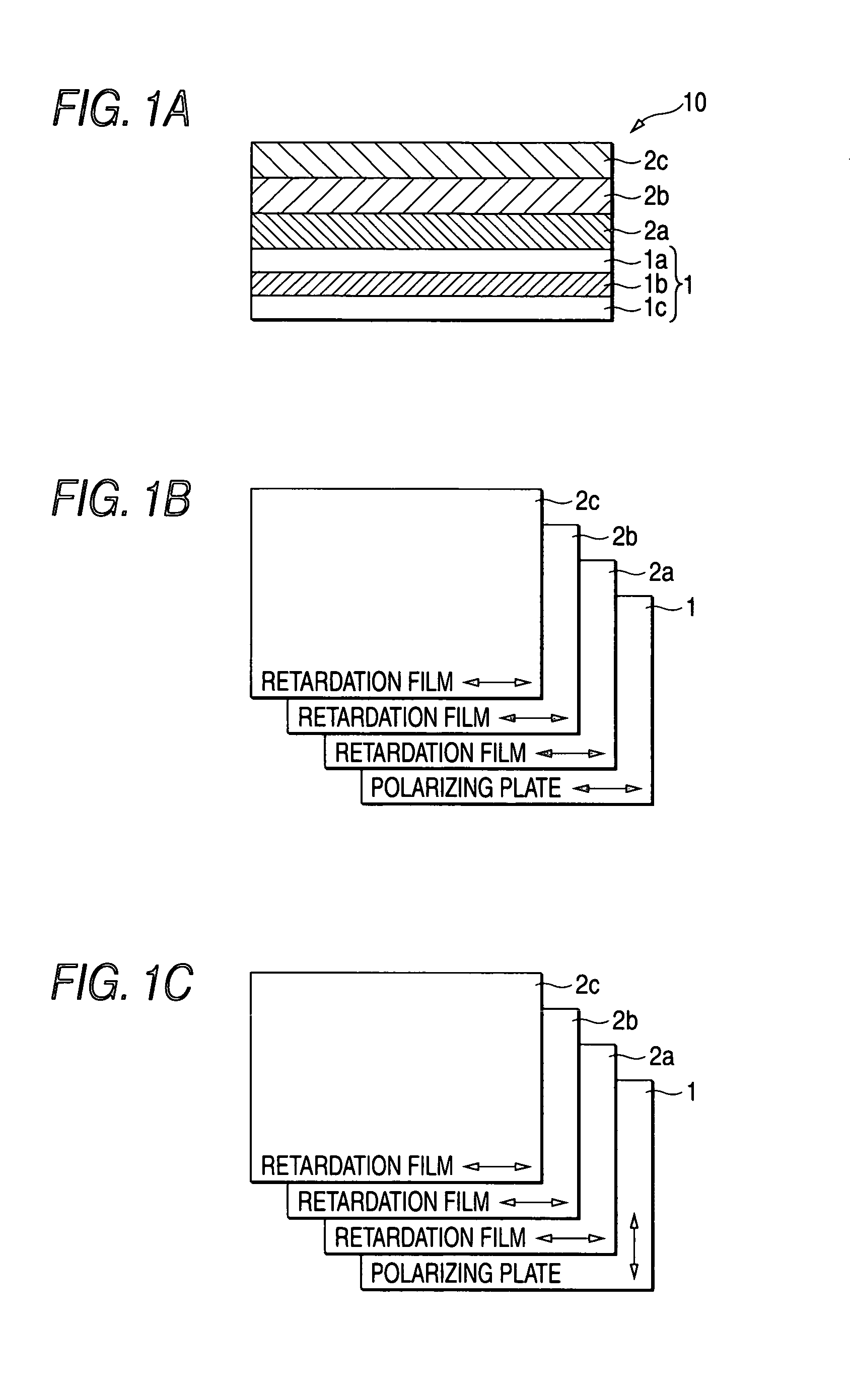
[0122]The retardation films 2a, 2b, and 2c were prepared by means of stretching the polycarbonate film. The Nz value of the retardation film 2a was about 0.86; the Nz value of the retardation film 2b was about 0.5; and the Nz value of the retardation film 2c was about 0.14. The total of the Nz values was essentially 1.5. The in-plane retardation Re1 of each of the retardation films 2a, 2b, and 2c was 275 nm.

(Optical Film)

[0123]As shown in FIG. 1E, the materials were laminated by use of the adhesive, to thus have prepared the optical film 10.

(Liquid-Crystal Display Device)

[0124]By use of the thus-prepared optical film 10, two liquid-crystal display devices, such as those shown in FIGS. 3 and 4, were manufactured. The polarizing plate 3 identical with the polarizing plate 1 was used. The liquid-crystal panel included in the liquid-crystal display device fu...


PUM

PropertyMeasurementUnit
thickness-direction retardation Rthaaaaaaaaaa
thicknessaaaaaaaaaa

Abstract

An optical film includes: a polarizer having an absorption axis; and at least three retardation films, each having a slow axis, wherein the absorption axis of the polarizer intersects the slow axis of each of the at least three retardation films at right angles and is parallel to the slow axis of each of the at least three retardation films, the slow axis of each of the at least three retardation films are parallel to each other, a total amount of Nz value of each of the at least three retardation films, the Nz value being defined by formula (I), is half as many as the number of the at least three retardation films, and an in-plane retardation Re1 of each of the at least three retardation films, the in-plane retardation Re1 being defined by formula (II), ranges from 200 to 350 nm:Nz=(nx1−nz1) / (nx1−ny1)   (I)Re1=(nx1−ny1)×d1 .   (II)

Description

BACKGROUND OF THE INVENTION[0001]1. Field of the Invention[0002]The present invention relates to an optical film having a polarizer and at least three phase-difference films laminated thereon.[0003]2. Background Art[0004]A liquid-crystal display device of so-called TN mode, where liquid crystal having a positive dielectric anisotropy is twisted and horizontally aligned between mutually-opposing substrates, has hitherto been primarily used as the liquid-crystal display device. However, even when an attempt is made to display black in the TN mode, birefringence is induced by liquid crystal molecules in the vicinity of the substrates because of a driving characteristic of the liquid-crystal display device. As a result, leakage of light arises, to thereby pose difficulty in displaying perfect black. In contrast, in a liquid-crystal display device of IPS mode, liquid crystal molecules exhibit, in an inoperative state, homogeneous alignment where liquid-crystal molecules become essentiall...

Claims


Application Information

Patent Timeline
Patent Type & Authority Patents(United States)
IPC IPC(8): G02F1/1335
CPCG02F1/13363G02F1/134363G02F2413/03G02F2413/07
Inventor TASAKA, TOMOKI
Owner FUJIFILM HLDG CORP
Why Eureka
Try Eureka