

Ranging apparatus and ranging method
a ranger and a technology of ranging apparatus, applied in the direction of distance measurement, surveying and navigation, instruments, etc., can solve the problem that the ranging apparatus of the discovery is unable to calculate the distance value of the pixels which have detected the delayed reflected, and achieve the effect of increasing the accuracy of the ranging process and accurately measuring the distance up to an obj
- Summary
- Abstract
- Description
- Claims
- Application Information
AI Technical Summary
Benefits of technology
Problems solved by technology
Method used
Image

Examples
first embodiment
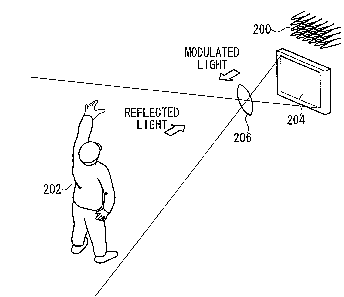
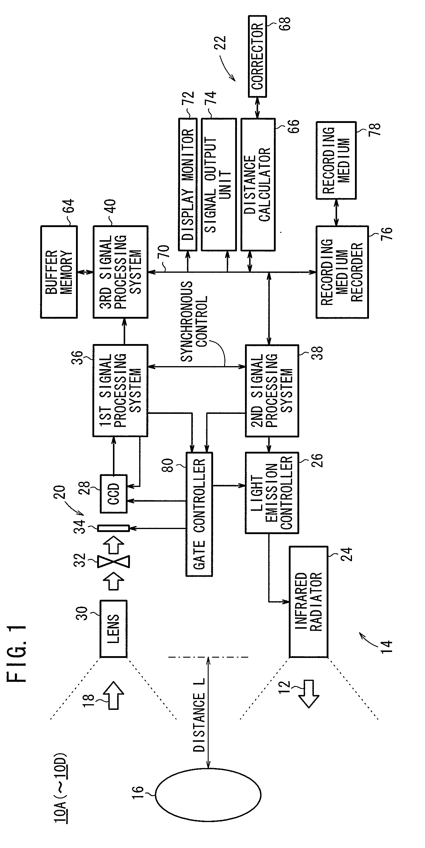
[0057]As shown in FIG. 1, a ranging apparatus 10A according to the present invention (hereinafter referred to as “first ranging apparatus 10A”) comprises a light-emitting unit 14 for emitting a modulated light 12 which has been intensity-modulated, a light-detecting unit 20 for detecting a reflected light 18 from an object 16 which has been irradiated with the modulated light 12, and a calculating unit 22 for calculating the distance from the first ranging apparatus 10A to the object 16 based on the phase difference between the modulated light 12 and the reflected light 18.
[0058]The light-emitting unit 14 comprises a light emitter (infrared radiator) 24 and a light emission controller 26 (sine-wave generator) for controlling the light emitter 24 to intensity-modulate a light emitted from the light emitter 24 and emit it as the modulated light 12. The light emitter 24 comprises an array of LEDs. The light emission controller 26 controls the light emitter 24 to emit a light that is in...
second embodiment
[0107]A ranging apparatus 10B according to the present invention (hereinafter referred to as “second ranging apparatus 10B”) will be described below with reference to FIGS. 9 through 11.
[0108]The second ranging apparatus 10B is similar to the first ranging apparatus 10A except as follows:
[0109]The gate controller 80 controls, with the gate pulses output thereby, the light emission controller 26 to emit the modulated light 12 in every third cyclic period of the modulated light 12, and also controls, with the gate pulses output thereby, the electrooptical shutter 32 or the electronic shutter of the image capturing device 28 to detect the reflected light 18 from the object 16 which has been irradiated with the modulated light 12, in every third cyclic period of the modulated light 12.
[0110]The distance calculator 66 does not correct the distance value if the ratio S of signal levels is greater than a first reference value T1. The distance calculator 66 adds a distance corresponding to ...
third embodiment
[0132]A ranging apparatus 10C according to the present invention (hereinafter referred to as “third ranging apparatus 10C”) will be described below with reference to a flowchart shown in FIG. 12 and a waveform diagram shown in FIG. 13.
[0133]The third ranging apparatus 10C is similar to the second ranging apparatus 10B except as follows:
[0134]The corrector 68 corrects the distance values with respect to those pixels of all the pixels wherein the phase difference φ between the modulated light 12 and the reflected light 18 falls in a predetermined range.
[0135]Specifically, a processing sequence of the third ranging apparatus 10C will be described below with reference to the waveform diagrams shown in FIGS. 6 and 13 and the flowchart shown in FIG. 12.
[0136]Steps S201 through S203 shown in FIG. 12 are identical to steps S101 through S103 of the processing sequence of the second ranging apparatus 10B, and will not be described in detail below.
[0137]In step S204, the distance calculator ca...
PUM
 Abstract
Description
Claims
Application Information