

Agricultural harvesting machine
- Summary
- Abstract
- Description
- Claims
- Application Information
AI Technical Summary
Benefits of technology
Problems solved by technology
Method used
Image

Examples
Embodiment Construction
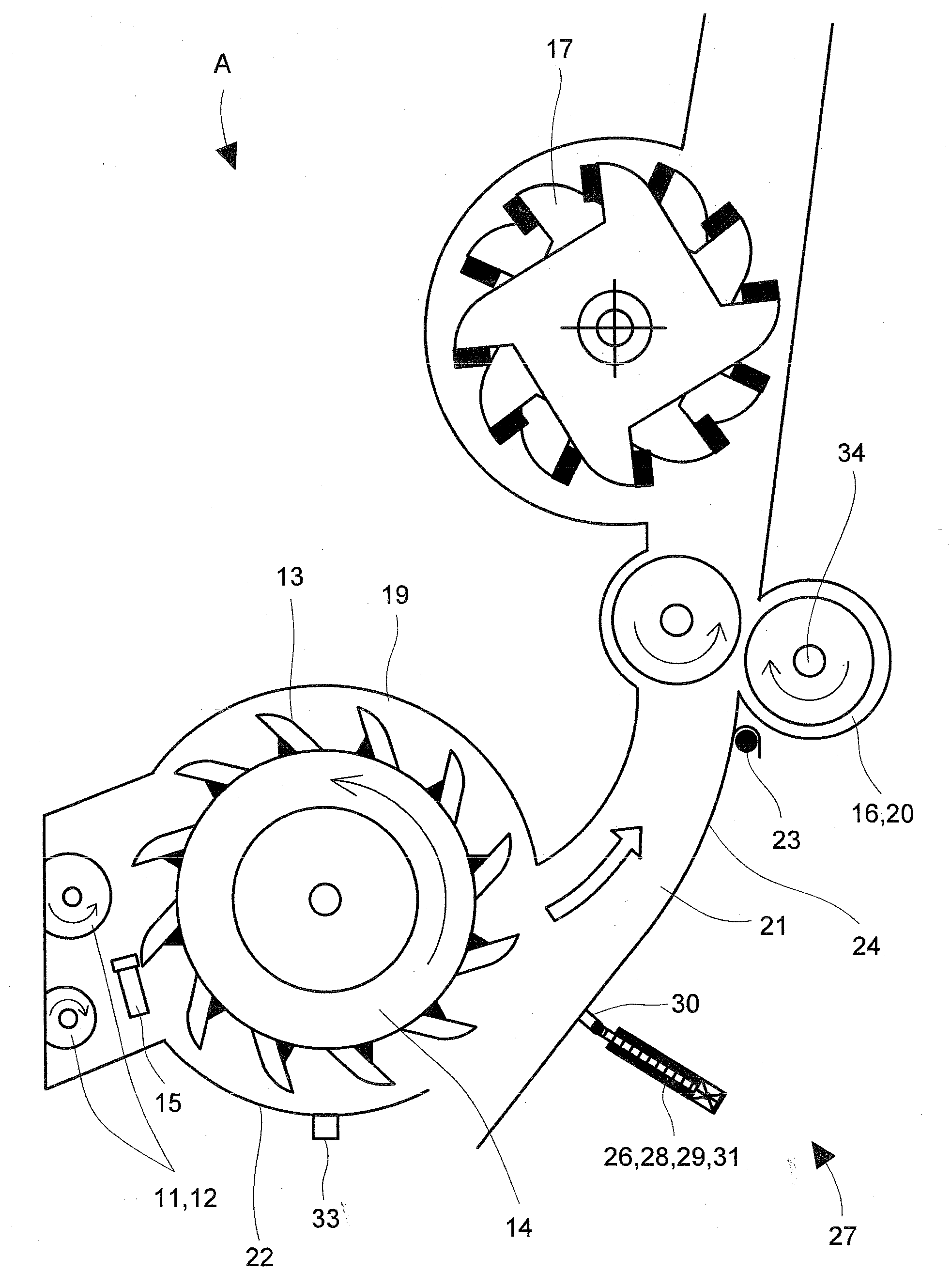
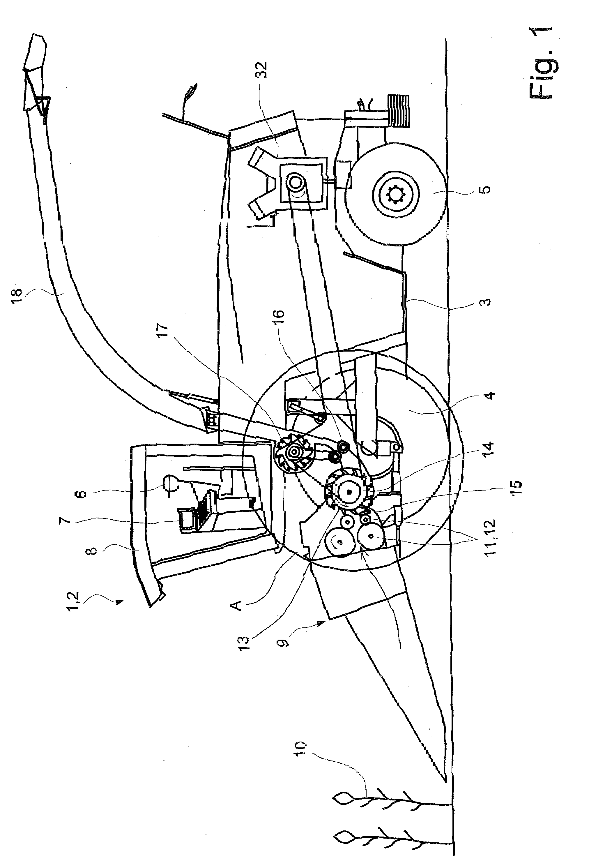
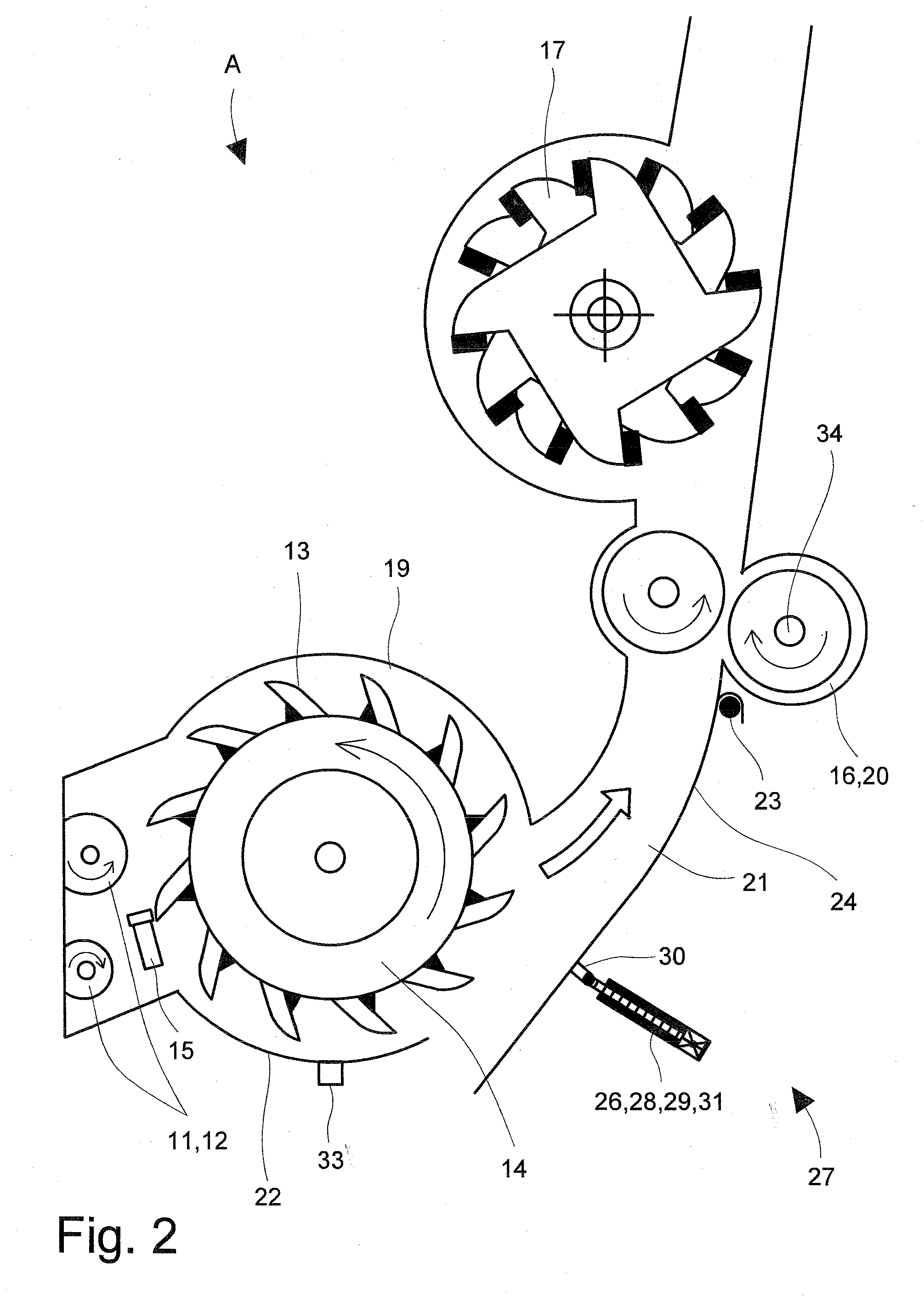
[0022]FIG. 1 shows a sectional side view of an agricultural harvesting machine 2 designed as a self-propelled forage harvester 1. It is built on a frame 3, which is carried by front and rear wheels 4, 5. Forage harvester 1 is operated by operator 6 using a control unit 7 in driver's cab 8, from where it is possible to see front attachment 9 attached to the front of forage harvester 1. In the working mode of forage harvester 1, front attachment 9 picks up crop material 10, cuts it and delivers it to downstream intake and compression rollers 11, 12. Intake and compression rollers 10 guide crop material 9 to downstream, rotating chopper drum 13 with blades 13 mounted on it which fragmentize crop material 10 on a shear bar 15.
[0023]Fragmentized crop material 10 is subsequently transferred to a post-fragmentation device 16, before it is drawn into post-accelerator 17. The task of post-fragmentation device 16 is to pound the corn kernels, when corn is the crop being harvested. Post-fragme...
PUM
 Abstract
Description
Claims
Application Information