
Deflectable Autoclavable Endoscope

an endoscope and autoclavable technology, applied in the field of endoscopes, can solve the problems of inability to achieve with great certainty, endoscopes exposed to considerable stress, contamination, etc., and achieve the effect of reliable function and additional mechanical protection

Active Publication Date: 2008-09-25
STORZ ENDOSKOP PROD GMBH
View PDF9 Cites 29 Cited by
  • Summary
  • Abstract
  • Description
  • Claims
  • Application Information

AI Technical Summary

Benefits of technology

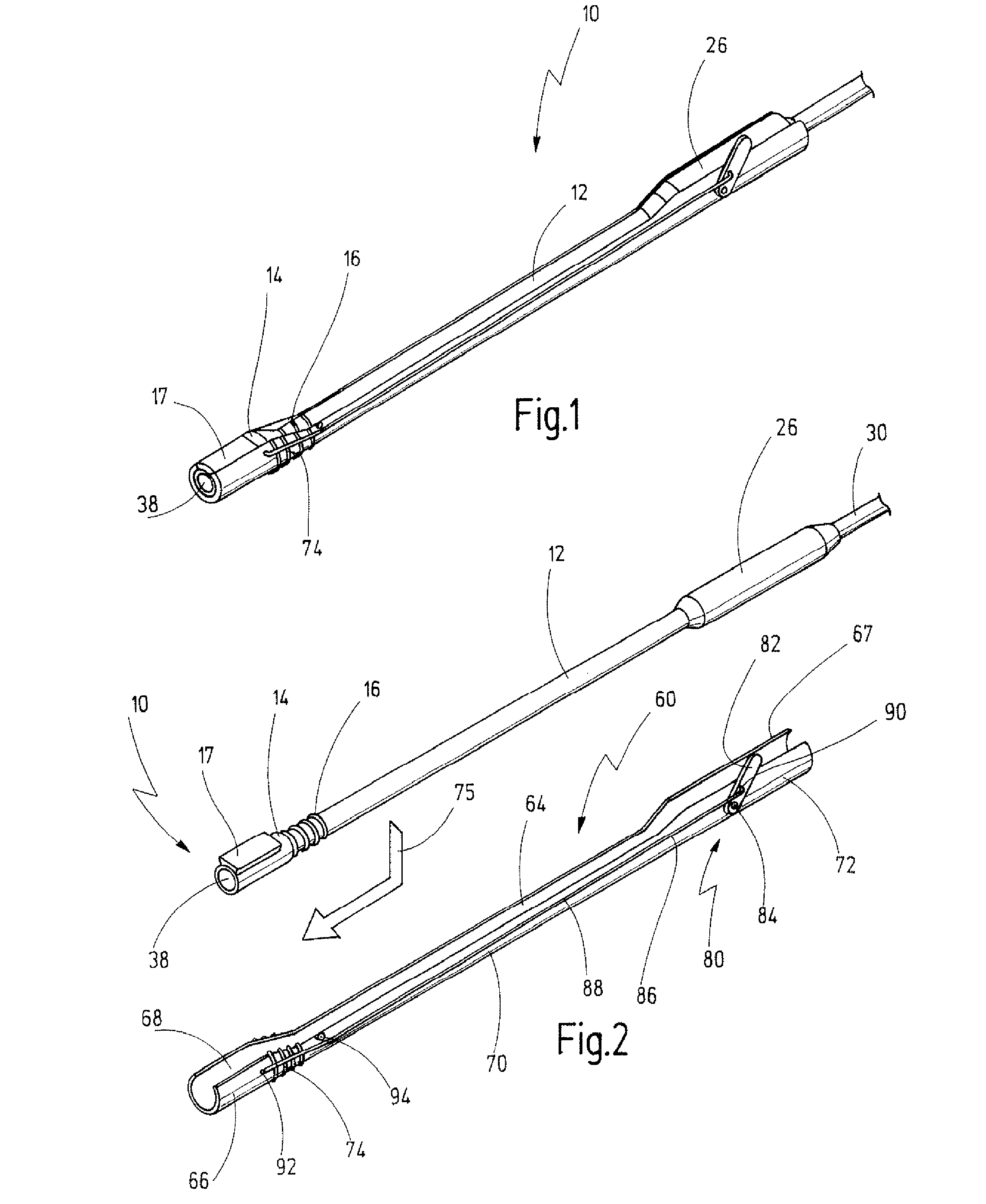
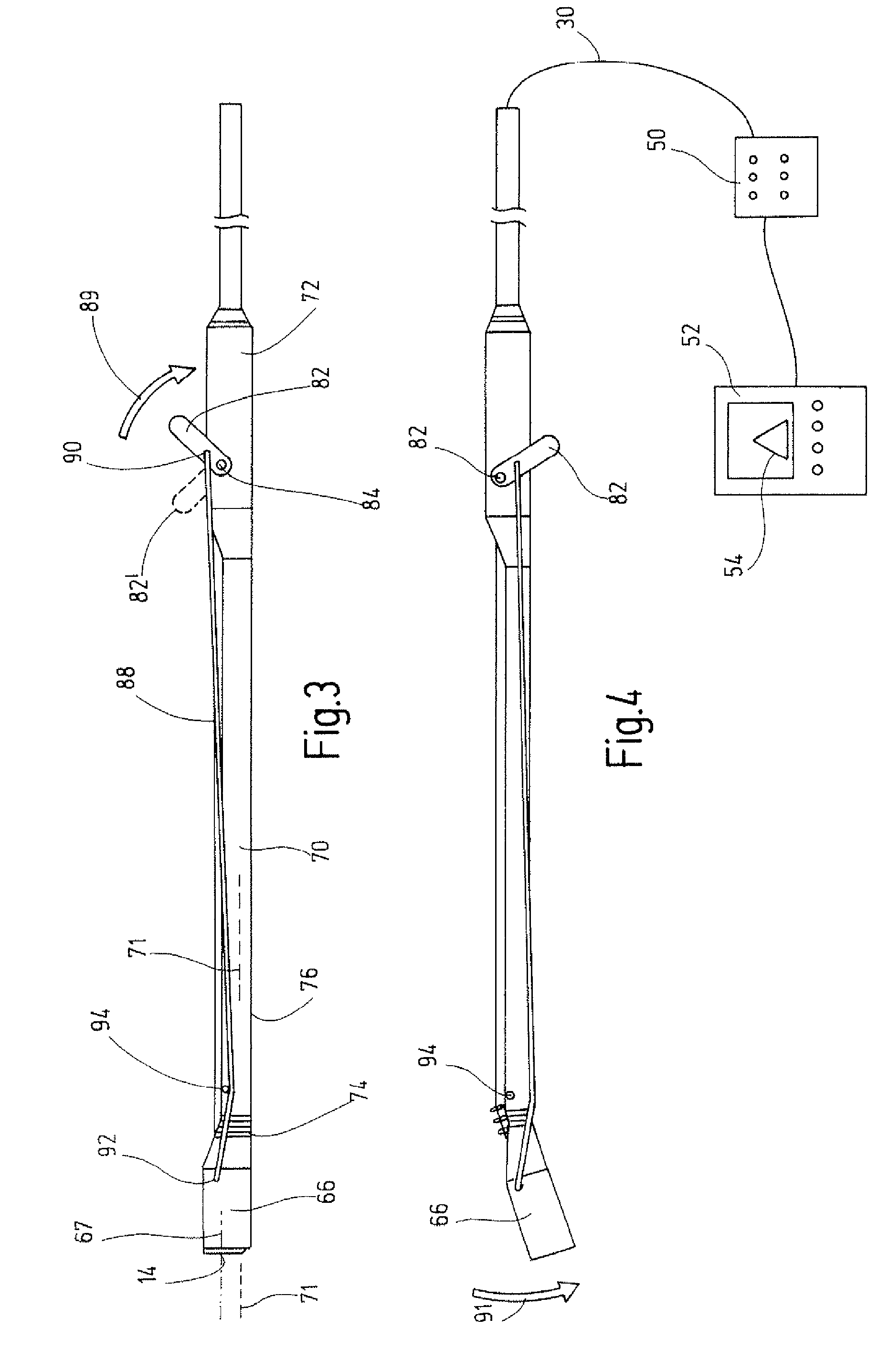
[0023]For the deflection, a separate part is applied, namely the outer part, which comprises the deflector mechanism. Since the outer part can be attached laterally onto the shaft or, conversely, the shaft can be inserted laterally into the outer part, handling is easy. It can be done, for example, by simple insertion, clipping or a snap-fit. By providing a distally deflectable end portion of the shaft, only a certain area of the shaft has to have a degree of flexibility in order to permit this deflection. This can also be achieved with relatively stiff or metal materials, for example by bellows-like formations or thinning of the material, such that the shaft does not have to be made entirely from a flexible material. In other words, the shaft can be made entirely of metal, as before, and simply has to show the flexibility at the deflection site in the distal area. The outer part contains the deflector mechanism via which the distal end portion of the shaft can be deflected after the outer part has been mounted laterally on the shaft, or vice versa.
[0076]These structural parts can be mechanically protected in the deflectable end portion and hermetically closed off from the outside, such that only cables, which carry the corresponding impulses, signals, light and the like, need to be routed through the deflection site and through the shaft to the proximal end. These cables can also be integrated sealingly into the inside face of the shaft in the deflectable area of the shaft, in order to ensure absolute leaktightness in this critical location and also to ensure additional mechanical protection.

Problems solved by technology

The shaft of the endoscope comes into direct contact with the tissue during use and is thus exposed to contamination.
As minimally invasive surgery is becoming increasingly more common, these cycles are being carried out several times a day, with the result that such endoscopes are exposed to considerable stresses, which they have to be able to withstand over a long period.
In flexible endoscopes, this cannot be achieved with any great certainty, since the flexible materials, mostly plastics, do not withstand these harsh conditions over the long term.
However, the problem of autoclaving arises here.
This endoscope is awkward to handle, since the sterile tube has to be pushed onto the long thin shaft of the endoscope before each use, and this requires a certain skill.
It is not possible to exclude the possibility of the shaft being contaminated during these preparatory manoeuvres.
The risk of contamination is much greater when, after use, the tube is removed again from the shaft and discarded.
However, these procedures are very time-consuming and, after a large number of uses, there is the possibility of the aggressive chemical substances passing through the plastic wall of the core and penetrating into the interior of the core.

Method used


Image

  • Deflectable Autoclavable Endoscope
  • Deflectable Autoclavable Endoscope
  • Deflectable Autoclavable Endoscope

Examples


Embodiment Construction

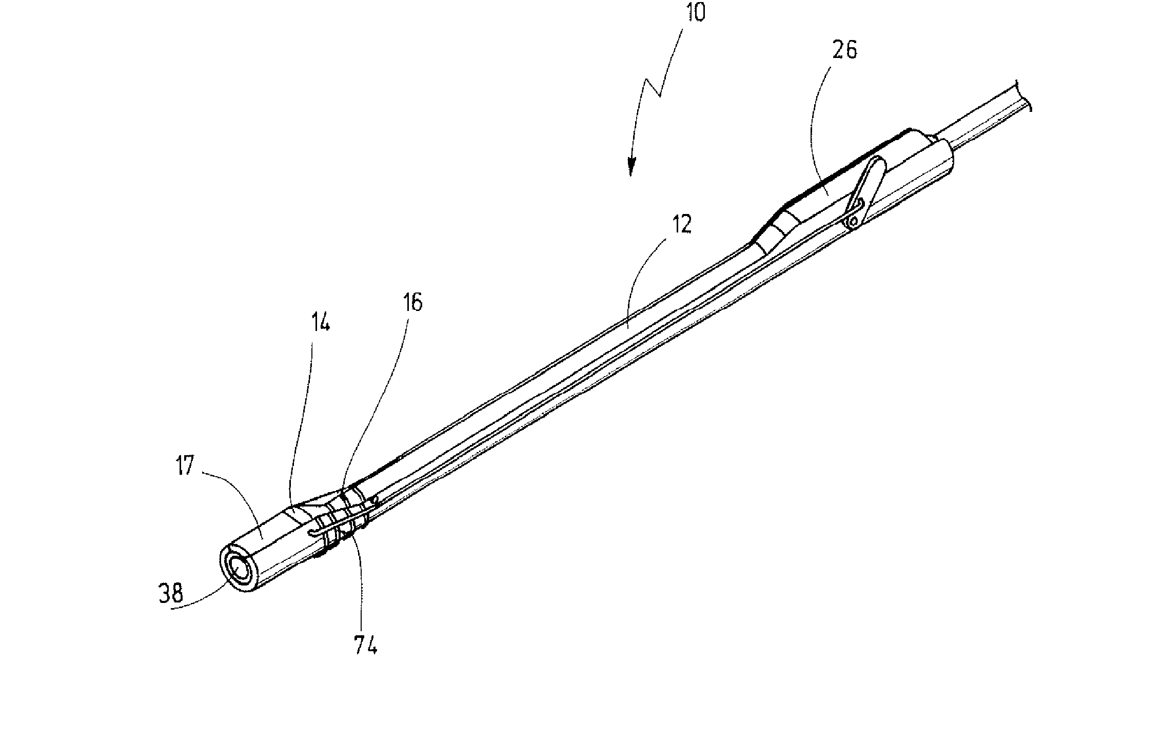
[0087]An endoscope shown in the figures is designated overall by the reference number 10.

[0088]The endoscope 10 has an elongate, rectilinear stiff shaft 12, which has a distal end portion 14.

[0089]The transition from the shaft 12 to the distal end portion 14 comprises a flexible area 16. This is obtained by a relative thinning of the material of the shaft wall in this area. In this area, a resetting element 18 in the form of a helical spring 20 is placed around the shaft 12. Formed on the outside of the distal end portion 14 there is an attachment 17 which, as can be seen in particular from FIG. 6, has an approximately dovetail-shaped contour.

[0090]As will be seen in particular from the view in FIG. 5, the external diameter 22 of the shaft 12 is smaller than tire external diameter 24 of the distal end portion 14.

[0091]As will also be seen from FIG. 5, the shaft 12 has a proximal portion 26 whose external diameter 28 is likewise greater than the external diameter 22 of the shaft and ...


PUM


Abstract

An endoscope has a shaft housing a lighting and an image transmission system and said endoscope being designed to be autoclavable. The shaft has a distal end portion which is made deflectable. An outer part is provided which is attached to said shaft. The outer part has a deflector mechanism for deflecting said deflectable distal end portion of said shaft and said outer part can be attached to said shaft by being releasably mounted laterally onto said shaft.

Description

BACKGROUND OF THE INVENTION[0001]The invention relates to an endoscope with a shaft that houses a lighting and image transmission system, the endoscope being designed to be autoclavable.[0002]Endoscopes of this kind are widely known and are used in minimally invasive surgery. In rigid endoscopes, the shaft is made of a stiff material, in most cases medical-grade steel. In flexible endoscopes, the shaft, at least in the flexible area, is made of a pliant plastic material.[0003]The shaft of the endoscope comes into direct contact with the tissue during use and is thus exposed to contamination. For economic reasons, it is of advantage to be able to use such endoscopes more than once.[0004]For this purpose, the endoscopes initially have to be cleaned after use and thereafter have to be sterilized, this usually being done by an autoclaving process.[0005]In autoclaving, the endoscope is exposed to relatively high temperatures. In what is called flash autoclaving, it is exposed to temperat...

Claims


Application Information

Patent Timeline
Patent Type & Authority Applications(United States)
IPC IPC(8): A61B1/00A61B1/005
CPCA61B1/00071A61B1/00105A61B1/00147A61B1/121A61B1/0056A61B1/01A61B1/00183
Inventor IRION, KLAUS M.RUEGG, THOMAS
Owner STORZ ENDOSKOP PROD GMBH
Learn More