Method and apparatus for decoking tubes in an oil refinery furnace

a technology of oil refinery furnace and decoking tube, which is applied in lighting and heating apparatus, separation processes, instruments, etc., can solve the problems of furnace tube fouling, and furnace tube fouling of each pass

Inactive Publication Date: 2008-09-25
OSBORNE III LESLIE D
View PDF16 Cites 14 Cited by
  • Summary
  • Abstract
  • Description
  • Claims
  • Application Information

AI Technical Summary

Benefits of technology

[0017]A control system for performing a global-decok

Problems solved by technology

Coking up of furnace tubes in multi-pass oil furnace tubes is a problem that impacts on the day-to-day operations of a typical oil refinery.
During normal operation of the tube furnace the furnace tube of each pass becomes fouled by coke deposits on the interior surface of the tubes.
As this fouling process progresses, the furnace efficiency drops, and progressively more severe furnace conditions are required to heat the incoming feed to coking temperature.
As a result of this internal furnace tube fouling, it is necessary to periodically decoke the furnace tubes.
A similar problem occurs in multi-pass oil refinery tube furnaces used to heat crude oil prior to entry into downstream fractionator plant, and petroleum oil furnaces used to heat petroleum feed to be fed into downstream vacuum distillation plant; all these tube furnaces, which typically comprise of a plurality of passes (“multi-pass

Method used


Image

  • Method and apparatus for decoking tubes in an oil refinery furnace
  • Method and apparatus for decoking tubes in an oil refinery furnace
  • Method and apparatus for decoking tubes in an oil refinery furnace

Examples


first embodiment

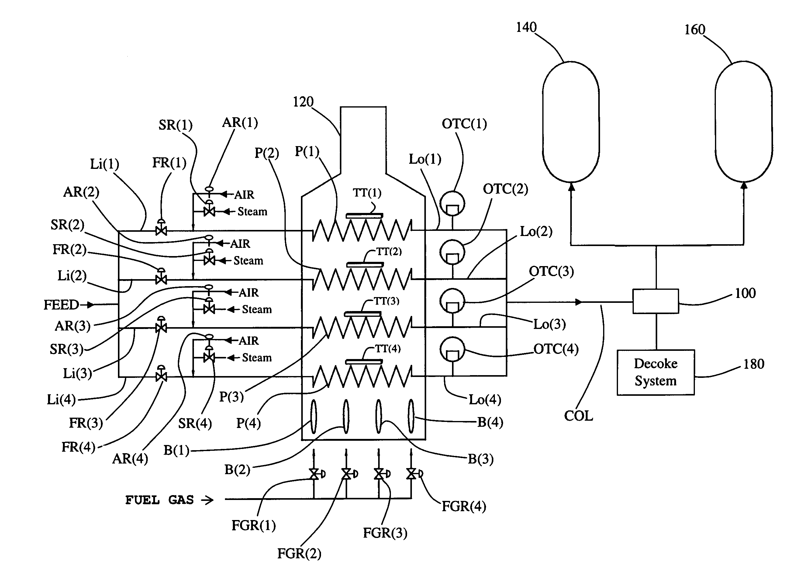
[0039]FIG. 3 shows a not-to-scale schematic layout of the present invention in which a 3-way valve 100 is deployed immediately downstream of a tube furnace 120 and is used to direct removed carbon deposits in the combined output line COL to the decoke system 180 (e.g., during decoke operations) or to direct heated feed (a petroleum product) to the delayed coke plant as represented respectively by first and second coke drums 140 and 160, which operate in batch-continuous mode. The tube furnace 120 is shown made up of plurality of passes, in this example of a tube furnace there are four passes, i.e., passes P(1) through P(4). It should be understood that the number of passes in the tube furnace 120 can vary, can be more than four or can be less than four. Explanation of the part numbers and labels shown in FIG. 3 are found in Table 1. The term “multi-pass” and “plurality of passes” are regarded as equivalent terms.

[0040]It should be expressly understood that the present invention is n...

second embodiment

[0052]FIG. 9 shows a not-to-scale schematic layout of the present invention in which a 4-way valve 105 is deployed downstream of a tube furnace 120. During normal operation the four-way valve 105 is set to direct the feed in combined output line COL to one of a pair of delayed coke drums 140 and 160. As explained previously, the delayed coke drums 140 and 160 operate in continuous-batch mode. The tube furnace 120 is multi-pass tube furnace made up of a plurality of passes, in this example of a tube furnace there are four passes, i.e., passes P(1) through P(4). It should be understood that the number of passes in the tube furnace 120 can vary, can be more than four or can be less than four. Explanation of the part numbers and labels shown in FIG. 9 are found in Table 1.

[0053]Still referring to the second embodiment, furnace 120 continues operating so long as the number of passes that meet or exceed their allocated SIFR does not fall below a predetermined number. For example, for a fu...

third embodiment

[0056]With reference to FIG. 13, which speaks to the present invention, a three-way valve 100 is located on every output line Lo(1 through N) thereby allowing each pass to be decoked separately.


PUM


Abstract

A control system for performing a global-decoke of a tube furnace comprising a plurality of passes.

Description

CROSS-REFERENCE TO RELATED APPLICATIONS[0001]This application claims the benefit of priority from U.S. Provisional Patent Application Ser. No. 60 / 896,851 (filed Mar. 23, 2007), which is incorporated herein by reference in its entirety.STATEMENT REGARDING FEDERALLY SPONSORED RESEARCH OR DEVELOPMENT[0002]Not Applicable.FIELD OF THE INVENTION[0003]This invention generally relates to removing coke, in the form of coke-buildup, from the interior tube walls of a multi-pass oil refinery tube furnace, which finds wide usage in various places in an oil refinery.BACKGROUND OF THE INVENTION[0004]Coking up of furnace tubes in multi-pass oil furnace tubes is a problem that impacts on the day-to-day operations of a typical oil refinery. For example, in the delayed coking process, a petroleum residuum (also referred to as “feed”) is heated to coking temperature in a tube furnace, and the heated residuum is then passed to a coking drum (often referred to as a “delayed coking drum”) where the heated...

Claims


Application Information

Patent Timeline
IPC IPC(8): G05B21/00
CPCC10G9/16C10G9/206F28G15/00F28G13/00F28D2021/0059F28G15/003
Inventor OSBORNE, LESLIE D.
Owner OSBORNE III LESLIE D
Why Eureka
Try Eureka