Electronic System Condition Monitoring and Prognostics

a technology of electro-mechanical systems and condition monitoring, applied in the field of modeling, predicting, and mitigating the failure of electrical systems, can solve the problems of dramatically reducing the value of the system, the failure rate of the electro-mechanical system never reaching zero, and the system failure can become more acute, so as to improve the prediction accuracy of the inference engine, and the effect of reducing the potential failure rate of the electronic system

Inactive Publication Date: 2008-09-25
MASSACHUSETTS INST OF TECH +1
View PDF4 Cites 69 Cited by
  • Summary
  • Abstract
  • Description
  • Claims
  • Application Information

AI Technical Summary

Benefits of technology

[0007]Further, a method for monitoring and predicting the condition of an electronic system comprises constructing a component model, predicting a state and a likelihood of failure of the electronic system using an inference engine based on the component model, and creating new data to improve prediction accuracy of the inference engine based on predictions from the inference engine.

Problems solved by technology

As new technology is integrated into day-to-day operations, the problem of system failure can become more acute.
If a complex system fails, the cost to diagnose and fix the problem can dramatically reduce the system's value.
While every system strives to be robust and reliable, failure rates for electro-mechanical systems will never reach zero.
Naïve self-diagnosing technology is all around us already: operating systems tell the user that they have “encountered” an error, cellular phones estimate signal strength with “bars,” and GPS navigation units tell the user that they have “lost satellite reception.” However, these diagnoses are typically opaque and late: the user only learns of the failure after it has occurred and must figure out for himself what mitigating action to take.

Method used


Image

  • Electronic System Condition Monitoring and Prognostics
  • Electronic System Condition Monitoring and Prognostics
  • Electronic System Condition Monitoring and Prognostics

Examples


Embodiment Construction

[0018]Reference will now be made in detail to exemplary embodiments of the invention, examples of which are illustrated in the accompanying drawings.

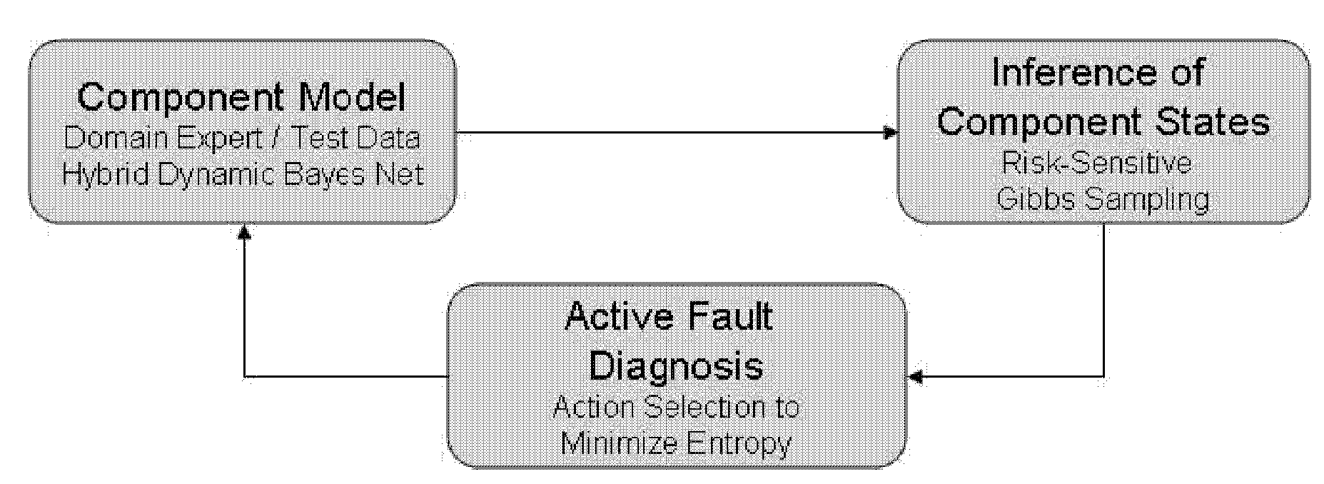
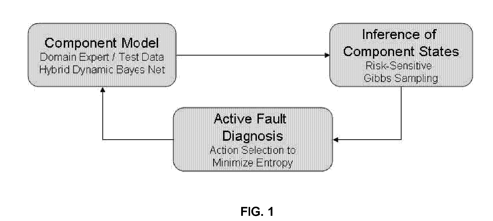
[0019]Complex systems, including complex electromechanical systems can fail. Instead of investing endless energy and resources into making systems perfectly robust, failures can be mitigated by modeling the system and predicting failures. The present teachings contemplate a system that takes knowledge from domain experts as well as observed data and creates a model-based inference system for predicting failure in such systems.

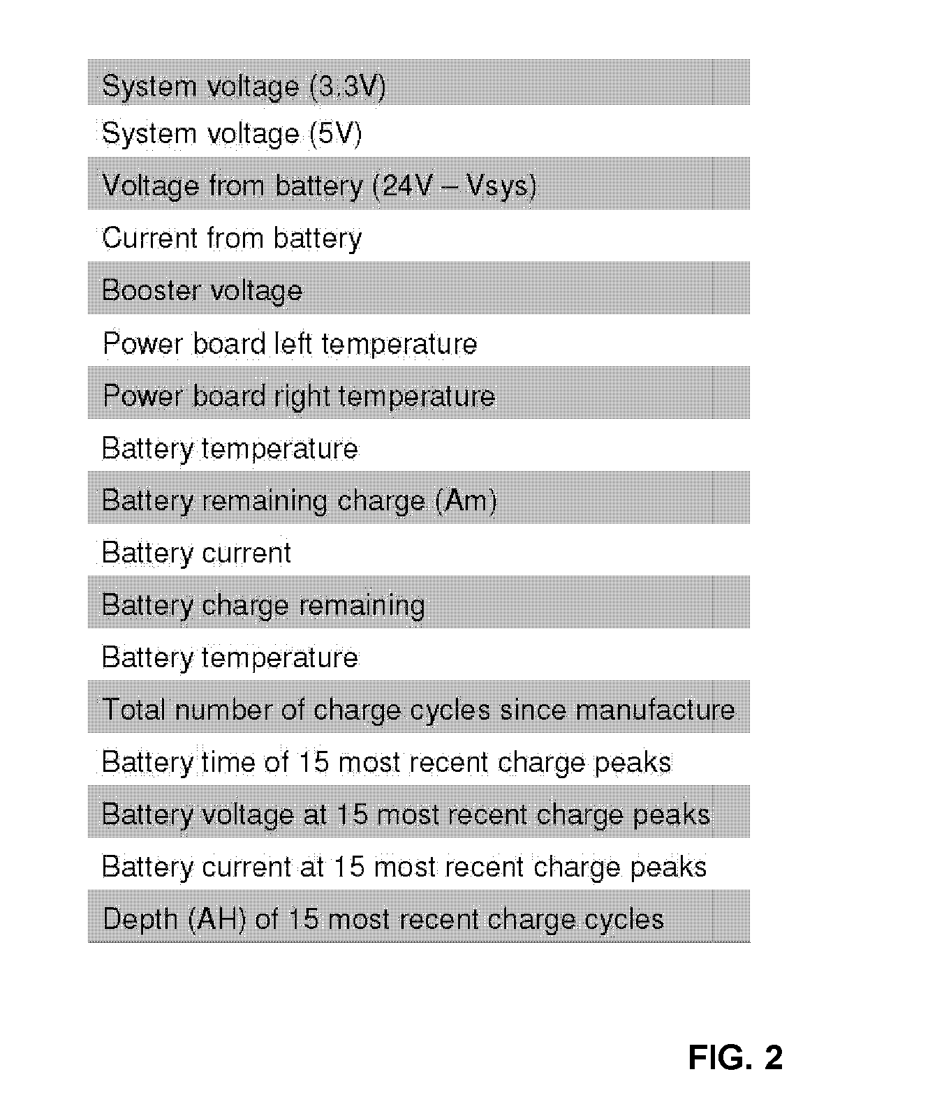
[0020]In certain exemplary embodiments of the present teachings, a platform for the system can include a power system for a remote vehicle such as, for example, a battery for an iRobot PackBot® EOD Tactical Mobile Robot. Analysis of PackBot® failure data suggests that the power system is the most common failure point, and that those failures can strand the robot in undesirable positions. A system in accordance with...


PUM


Abstract

A system for monitoring and predicting the condition of an electronic system comprises a component model, an inference engine based on the component model, and an action selection component that selects an action based on an output of the inference engine.

Description

[0001]This application claims priority to U.S. Provisional Patent Application Ser. No. 60 / 895,752 filed Mar. 20, 2007 and U.S. Provisional Patent Application Ser. No. 61 / 022,785 filed Jan. 22, 2008. The entire content of both applications are incorporated herein in their entirety.FIELD[0002]The present teachings relate to modeling, predicting, and mitigating failure of electrical systems, for example in power systems of remote vehicles such as mobile robots.BACKGROUND[0003]As new technology is integrated into day-to-day operations, the problem of system failure can become more acute. If a complex system fails, the cost to diagnose and fix the problem can dramatically reduce the system's value. While every system strives to be robust and reliable, failure rates for electro-mechanical systems will never reach zero. Instead, failure risk can be more effectively mitigated by engineering systems that can predict and diagnose their own failures, allowing users to take mitigating action be...

Claims


Application Information

Patent Timeline
Patent Type & Authority Applications(United States)
IPC IPC(8): G06N5/04
CPCG06N7/005G01R31/367G01R31/392G06N7/01
Inventor ROSENSTEIN, MICHAEL TODDADAMS, BRYAN PAULROY, NICHOLAS GEORGE DILIP
Owner MASSACHUSETTS INST OF TECH
Why Eureka
Try Eureka