
Brewing element with a central inlet

a technology of brewing element and central inlet, which is applied in the direction of tea, beverage vessels, domestic applications, etc., can solve the problems of increasing the cost of producing brewing machines and the cost to consumers, and achieve the effect of excellent humidity buffer

Active Publication Date: 2008-10-02
CONCEPT & DESIGN
View PDF11 Cites 13 Cited by
  • Summary
  • Abstract
  • Description
  • Claims
  • Application Information

AI Technical Summary

Benefits of technology

[0006]The present invention improves on the contemporary art by providing a new type of capsule that eliminates the need for rigid and complicated construction of the brewing element or the associated structure, such as a special rigid chamber, which is ordinarily needed to firmly hold the capsule in place in an espresso machine during the preparation process.
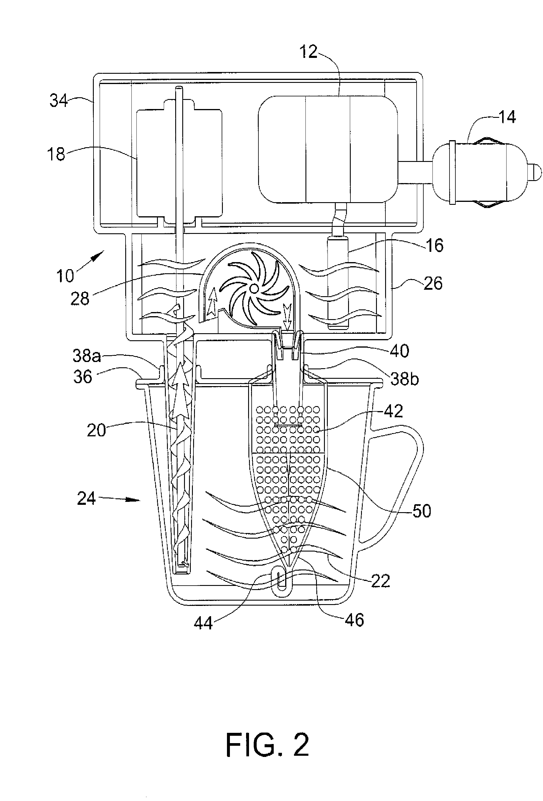
[0013]In one embodiment of the present invention, the capsule comprising the brewing element is toroidal-shaped. In another embodiment of the present invention, the capsule is tubular-shaped and made from aluminum which has ideal characteristics for the purpose of providing a self-supporting brewing element. Both these embodiments share the advantage of being able to withstand high pressure without any external support, so they can be integrated within a plastic cup as self-supporting brewing elements. By definition, use of aluminum in the tubular brewing element makes for an excellent humidity buffer between the water surrounding the tube and the powdered brewing ingredients contained within the tube.
[0014]Furthermore, since the tube comprising the brewing element is formed of one piece of aluminum, it can be hermetically and reliably scaled at its open distal end. It does not need an additional part to use as a cover to close this end. Folding the lower, distal end of the tube material upon itself also performs a perfect hermetic sealing of the tube. This new type of capsule will allow the production of a more flexible and greatly simplified mechanism for use in the next generation of espresso machines.

Problems solved by technology

Such rigid construction increases the cost of producing the brewing machine and the cost to the consumer is like-wise higher.

Method used


Image

  • Brewing element with a central inlet
  • Brewing element with a central inlet
  • Brewing element with a central inlet

Examples


Embodiment Construction

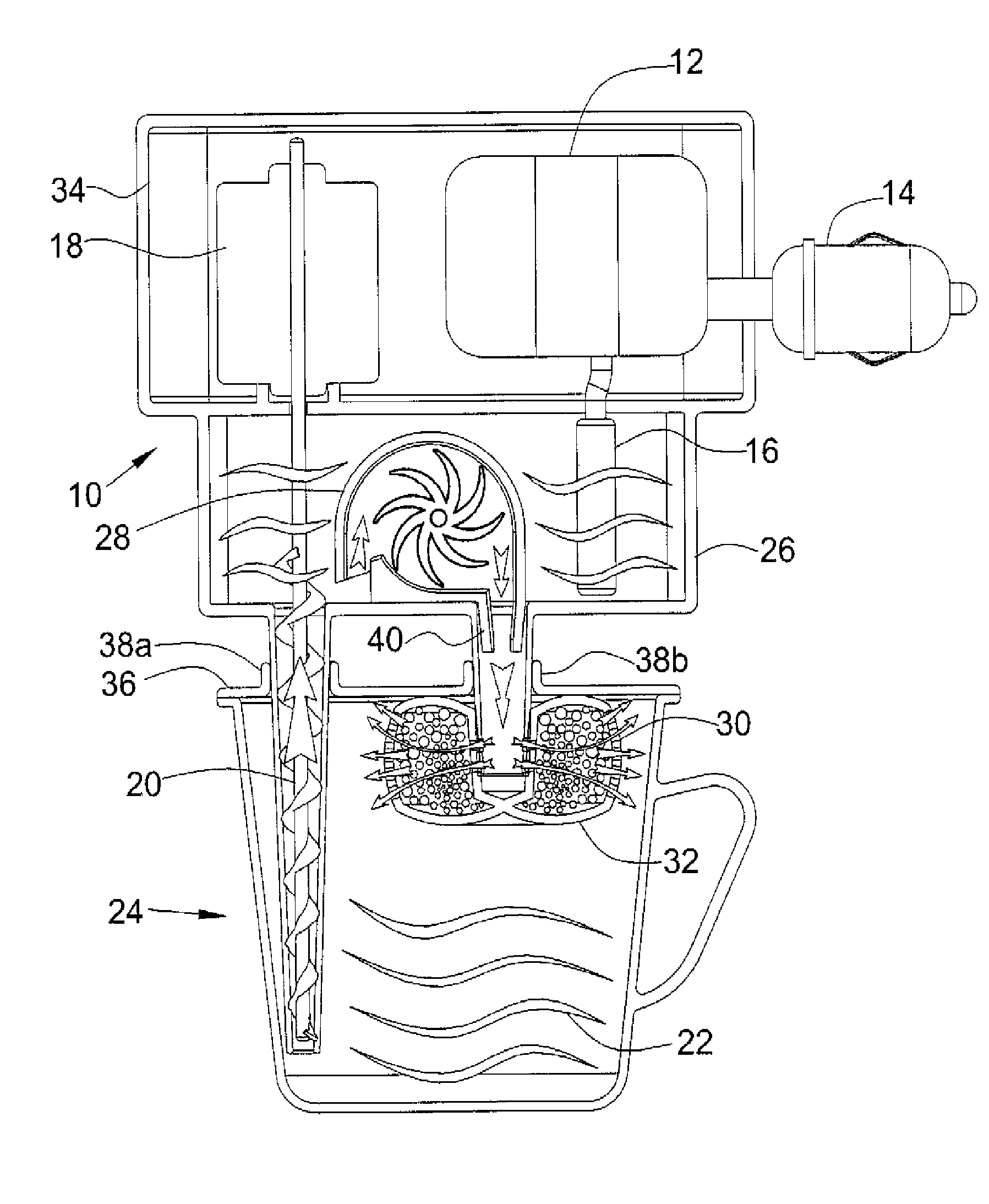
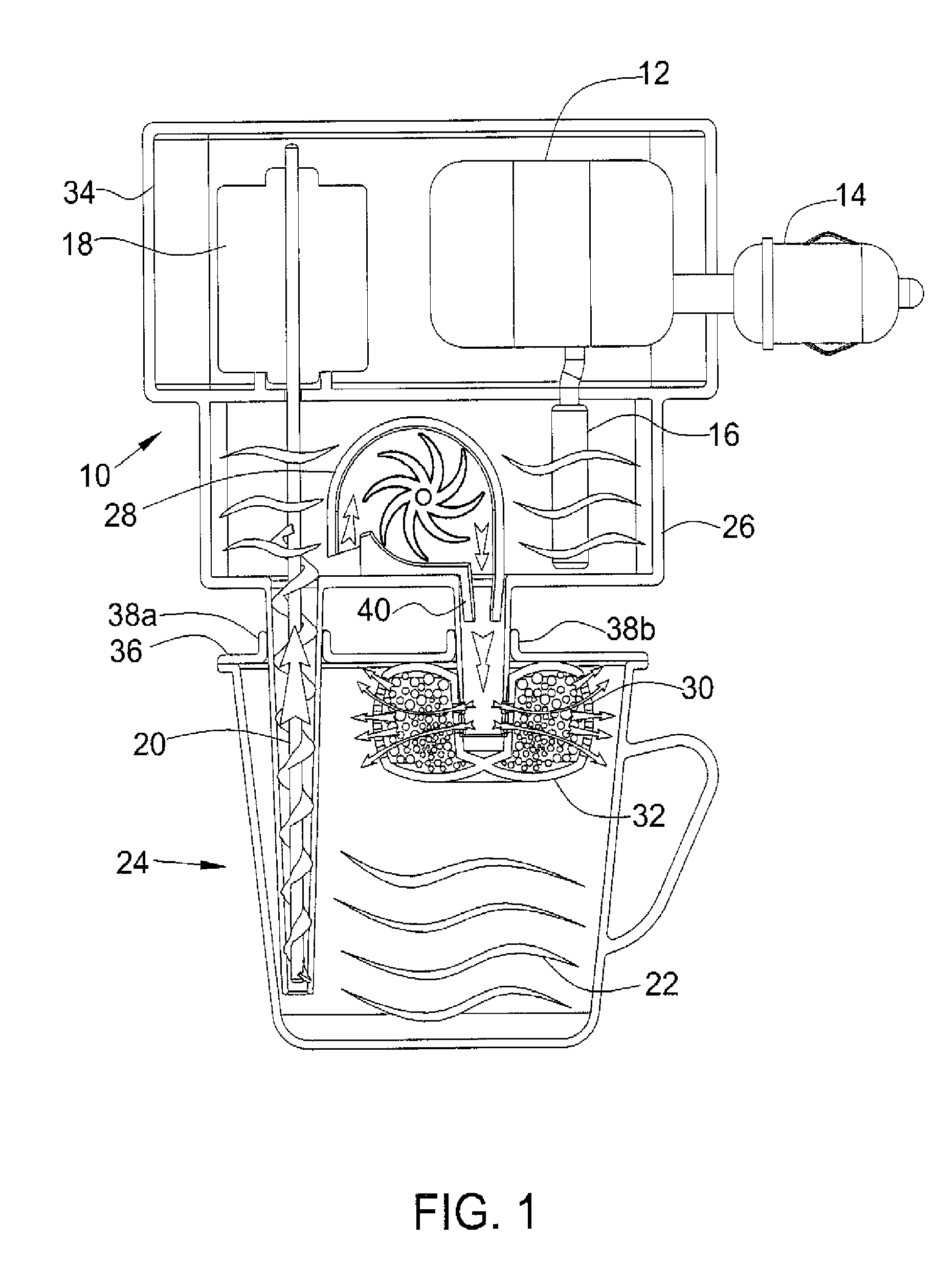
[0022]FIG. 1 is a cross-sectional view of an embodiment of the capsule of the present invention shown connected directly to a high-pressure water pump in a portable beverage brewing system.

[0023]The portable beverage brewing system comprises: a power and control unit 12 connected to a power source connector 14, for example, an auto cigarette lighter plug, and connected to a length of heater element 16 for heating the water for making a brew; a water suction pump 18 and suction tube 20 for drawing water 22 (shown as wavy lines) from a container 24, such as a cup, into the hot water pumping section 26; a high pressure pump 28 to create the necessary pressure to flush the water through the inner and outer envelope 30 of a brewing element 32, such as the toroidal capsule in one embodiment of the present invention; and a housing unit 34 for containing the various power and control components of the system which is shown mounted as a sealed unit 10 to the cup 24 where the brew is made.

[00...


PUM


Abstract

A portable beverage preparation device comprising a drink container containing a predetermined volume of a potable base liquid, at least one beverage preparation of a predetermined quantity; at least one sealed compartment for confining the beverage preparation, and a dispenser means for dispersing the at least one beverage preparation into the base liquid within the drink container; wherein the drink container and the at least one sealed compartment are in close physical proximity to each other and separated by at least one thin membrane which, when inwardly perforated by the dispenser means, disperses the at least one beverage preparation into the base liquid to make a beverage ready to drink.

Description

[0001]The present application is a Continuation-In-Part (CIP) of U.S. patent application Ser. No. 11 / 814,677 filed on Jul. 25, 2007 by the Applicant, the disclosure of which is hereby incorporated herein in its entirety by reference.FIELD OF THE INVENTION[0002]The present invention is related to beverage brewing elements and systems, and in particular, to a self-supporting brewing element with a central inlet disposed within a drinking container and usable in conjunction with espresso machines and portable beverage brewing Systems.BACKGROUND OF THE INVENTION[0003]Both pod and capsule portafilters used in espresso machines have a cylindrical chamber to hold the ground materials, such as coffee, used in brewing. The cylindrical envelope of this chamber is closed and the top and the base of the cylinder are perforated to allow pressurized water to enter the cylinder from one side flushing axially through the ground coffee and exiting as an espresso beverage from the other, perforated s...

Claims


Application Information

Patent Timeline
IPC IPC(8): A47J31/44A47J31/00
CPCA47J31/005
Inventor LEVIN, SHALOM
Owner CONCEPT & DESIGN
Learn More