

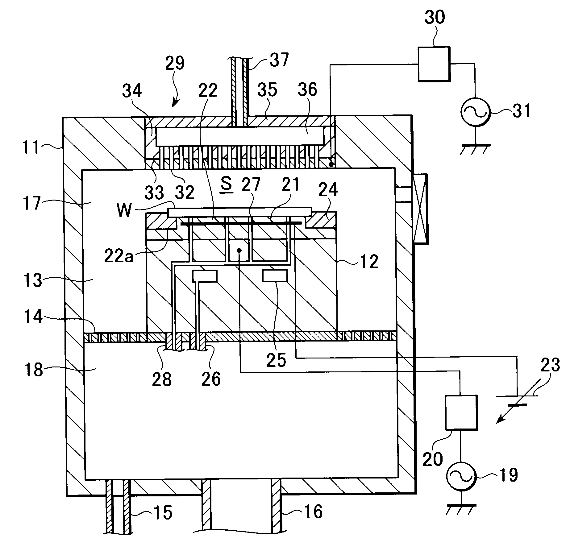
Substrate processing apparatus and substrate mounting stage on which focus ring is mounted
a technology of substrate and mounting stage, which is applied in the direction of electrical equipment, basic electric elements, electric discharge tubes, etc., can solve the problems that the fluorine coating fills in the depressions of the focus ring mounting surface, and the molecules constituting the heat transfer sheet cannot easily enter the gaps between the molecules constituting the fluorine coating
- Summary
- Abstract
- Description
- Claims
- Application Information
AI Technical Summary
Benefits of technology
Problems solved by technology
Method used
Image

Examples
example 1
[0061]First, in the substrate processing apparatus 42, the fluorine coating 41 is formed by FG-5010S135 produced by Fluoro Technology Co., Ltd, and the thickness thereof was set to 100 μm.
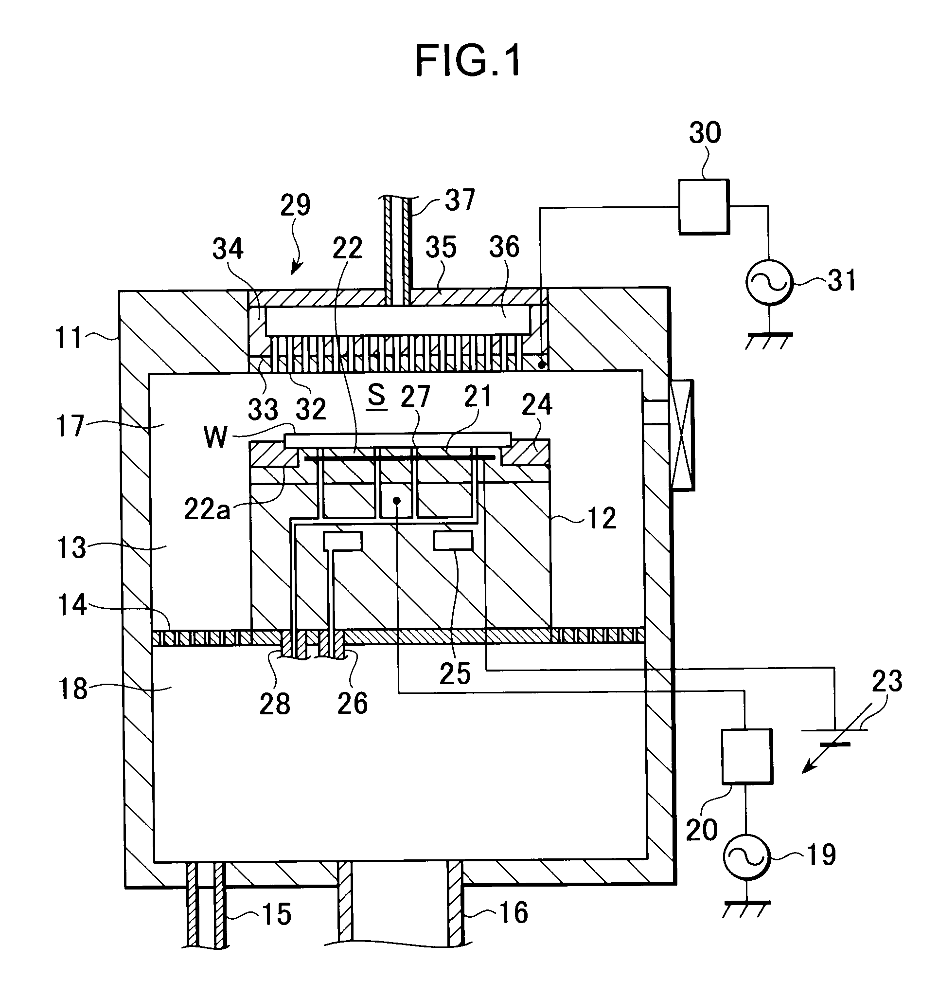
[0062]Next, as shown in FIG. 4, twelve heat transfer sheets 38 were disposed between the ring spacer 40 and the focus ring 24 and at regular intervals along the circumference of the focus ring 24.
[0063]In the substrate processing apparatus 42, etching processing was carried out on an oxide film of a wafer W five times, and then the focus ring 24 was removed from the susceptor 12 (focus ring removal test). At this time, the number of heat transfer sheets 38 still attached to the ring spacer 40 was checked, and whether each heat transfer sheet 38 was broken or not was determined. In removing the focus ring 24 from the susceptor 12, a spatula is inserted between the focus ring 24 and the electrostatic chuck 22. The number of times the spatula was inserted between the focus ring 24 and the electrostati...
example 2
[0070]First, as is the case with the example 1, the thickness of the fluorine coating 41 was set to 100 μm in the substrate processing apparatus 42. Next, etching processing was carried out on an oxide film of a wafer W, and the etch rate in the etching processing was measured. Then, etching processing was carried out on a BARC film (antireflection film) of another wafer W, and the etch rate in the etching processing was measured. Then, the results of the etching processing on the oxide film were summarized in FIG. 5A, and the results of the etching processing on the BARC film were summarized in FIG. 5B. It should be noted that the etching of the oxide film is high-power etching, and the etching of the BARC film is lower-power etching.
PUM
| Property | Measurement | Unit |
|---|---|---|
| thickness | aaaaa | aaaaa |
| thickness | aaaaa | aaaaa |
| temperature | aaaaa | aaaaa |
Abstract
Description
Claims
Application Information