Luggage

a luggage and luggage technology, applied in the field of luggage cases, can solve the problems of inconvenience in renting process, general dislike of travellers' tasks, carriers are helpful but not entirely free from inconveniences of their own, etc., and achieve the effect of greater striding space and greater pushing advantag

Active Publication Date: 2008-10-02
LEE IN OK
View PDF35 Cites 27 Cited by
  • Summary
  • Abstract
  • Description
  • Claims
  • Application Information

AI Technical Summary

Benefits of technology

[0036]When the steering wheel and handle are retracted, the luggage case can be carried by a handle placed at the long narrow surface like an ordinary carrying case. Preferably, when the wheeling system is activated and the case tilted backwards, the handle is also tilted backwards towards the user to give greater pushing advantage to the user and preferably is furthermore tilted away from the posterior case surface to allow for greater striding space. Preferably, the rear end wall surface of the case is recessed to provide additional striding space.
[0037]The case may be made of robust material not only for durability and protection of the contents, but to be able to provide a platform for carrying other pieces of luggage stacked on top of it. When the steering wheel and handle are in their active positions, the case can act as a cart / trolley for carrying other pieces of luggage. A simple braking system may be installed for safety and convenience purposes and an optional umbrella attachment may be provided on the handle bar if desired. This latter is particularly useful in the context of the trolley travel since it frees up the user to use both hands in pushing the case.

Problems solved by technology

Lifting and manually carrying luggage at airports, railway stations, hotels or other sites is a task which is generally disliked by travellers.
Rental luggage carts are available at certain sites of this kind but the renting process is itself an inconvenience and such carts do not remain with the traveller after leaving the site of rental.
Such carriers are helpful but are not entirely free of inconveniences of their own.
The carrier is not self-stabilized and it is not entirely self-supporting during movement.
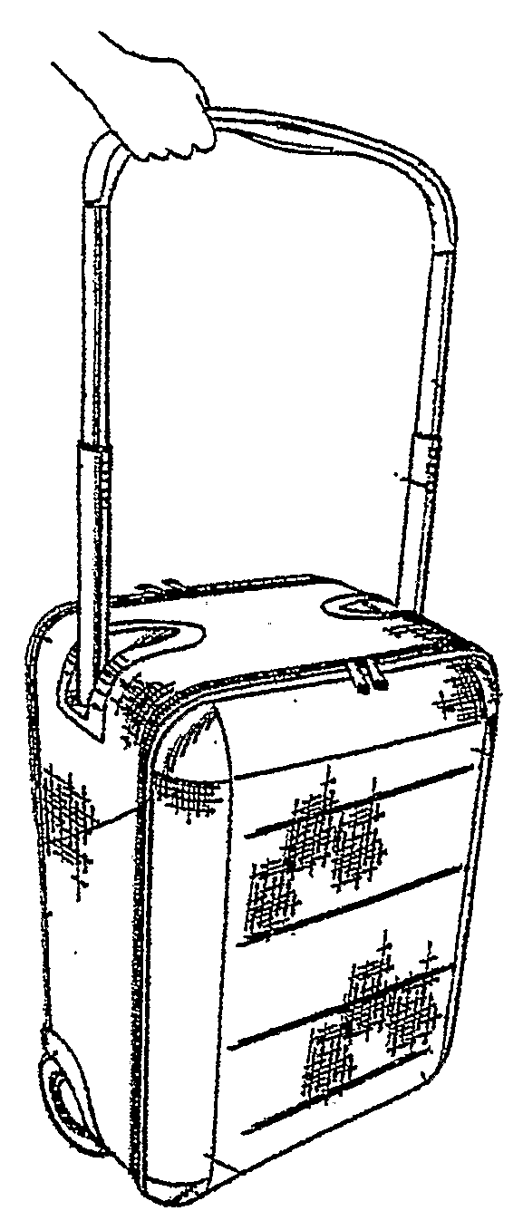
The instability of such a carrier when it is tilted to the travelling orientation and the pivoting movement which occurs when the handle is released make it unsatisfactory for certain purposes such as for transporting a small child along with a luggage case.
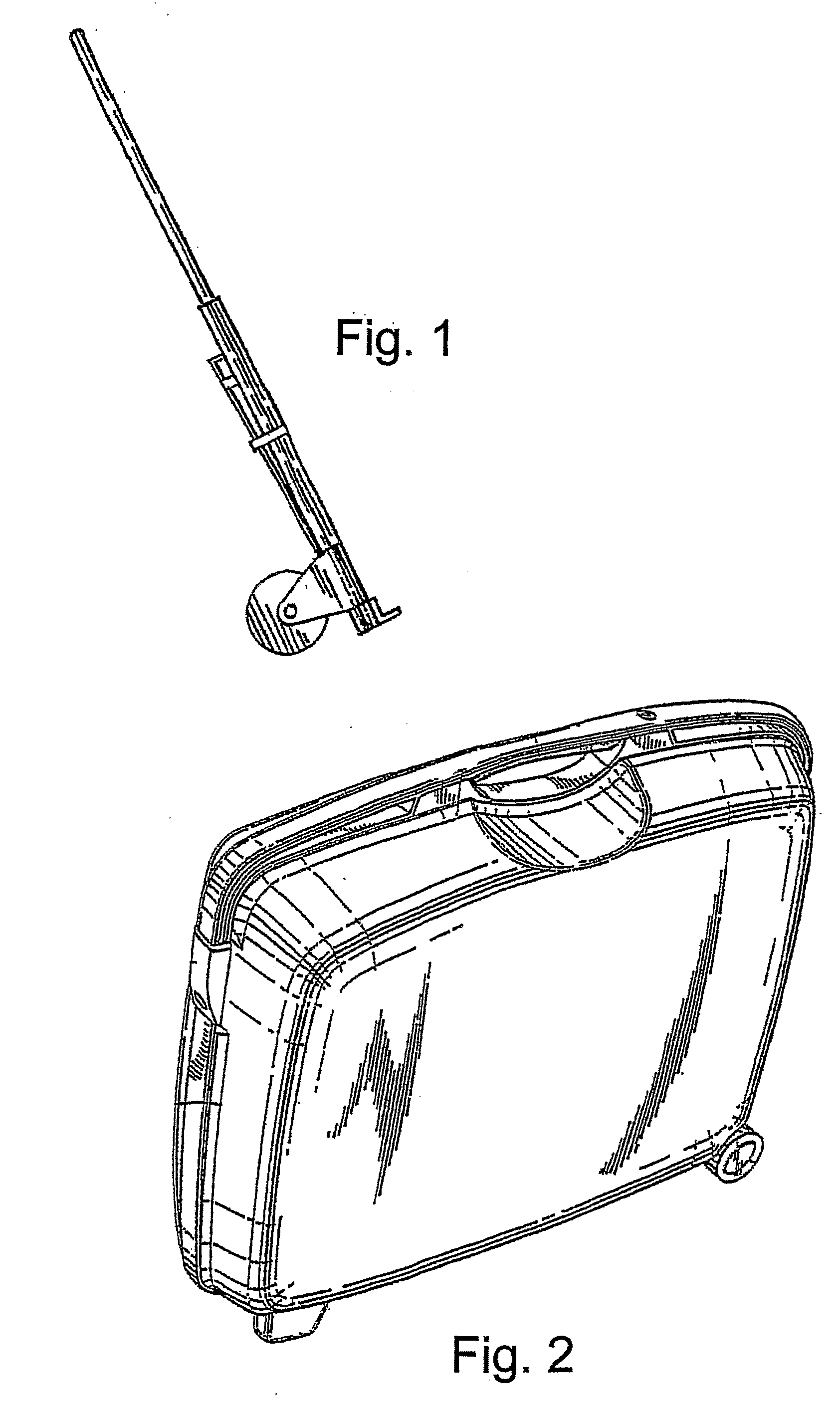
However the significant disadvantages are difficulty in manoeuvrability due to a long narrow base, instability due to the narrow base and a high centre of gravity that lead to a propensity for the case to topple to one side or the other.
Furthermore, the person pulling such a case generally has to lean over / stoop into an awkward posture to reach the pulling device and generally has inadequate stride clearance in choosing to pull the case behind them.
Lengthening the pulling device is a poor option since it further compromises steerability and stability.
However, widening the base increases the carrying angle and makes hand carrying the case less ergonomic and more laborious.
However, such a design is not self-supporting during transit and requires continuous lifting support from the user to hold it in the in the tilted state.
It is thus good for small and light cases but large size and / or heavy suitcases with this design are, in wheeled operation, cumbersome and tiresome to move around due to their considerable size and weight.
Indeed, for the elderly and infirm even the smaller and lighter cases with this design may still be a burden and whereas for short transits the burden may be minor, any such burden becomes increasingly irksome the longer the journey, more tiring the environment and more tired the individual is.
Thus though this 
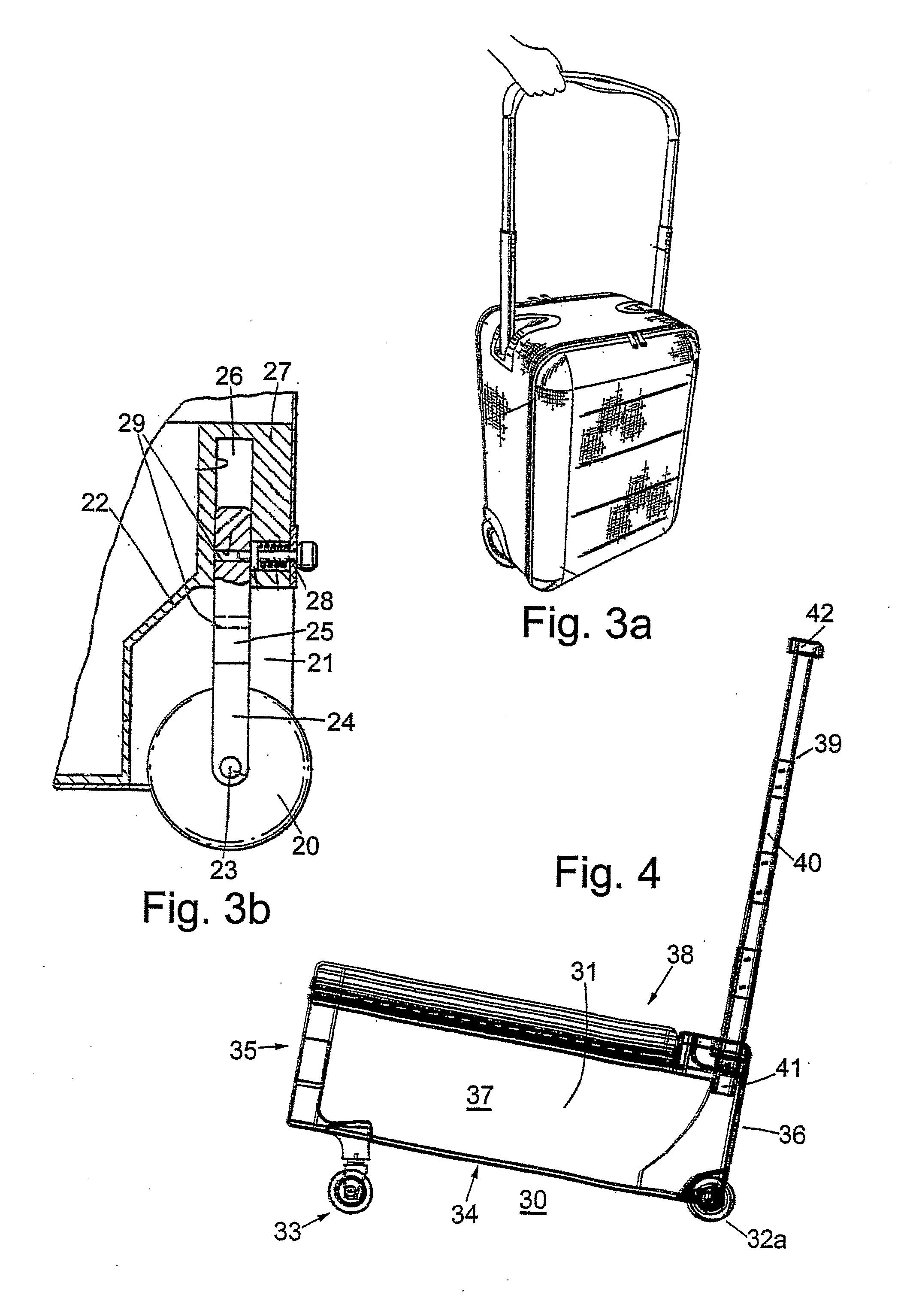
cart configuration of wheeled luggage case is relatively more stable in transit and ergonomic than cases with “wheels on long / narrow surface”; relatively manoeuvreable; and easy to activate it suffers from being not self-supporting during transit and may be strenuous with heavy loads and for long journeys and more difficult to use if the user's hand / arm has arthritis / deformity or other impairment.
Stride clearance can also be an issue and vibrations can be transmitted to the hand (felt) during case transit on rough surface (eg. roads).
This configuration of wheeled luggage case also do not facilitate piling up other items on the case (small surface area on top, makes whole luggage heavier because the extra load is placed away from the supporting wheels and towards the carrying hand).
However, it has a high center of gravity and wheels on short / narrow surface, thus is unstable and topples easily on cornering and uneven terrain.
Again vibrations are transmitted to hand (felt) during case transit on rough surface (eg. road) and again there is difficulty with piling up other items on the case (small surface area on top).
In all of the previous designs the narrow base and high centre of gravity mean that the cases are unstable.
However, there are practical inconveniences with potential damage to the exposed wheels during transfer and storage and difficulty in packing and unpacking with a non-stationary suitcase.
Also, stacking up of such cases within, for example, the cargo hold of a plane or coach becomes fraught with difficulty again because the cases cannot be relied upon to stay in place.
The multiple retractable wheels of these prior designs are flimsy, cumbersome and inconvenient to activate and retract.
Moreover, they make the whole case too heavy for practical purposes.
Since the weight of the case is concentrated on the pivotal points and / or support pins of the wheel retraction mechanisms, stronger and heavier materials are generally needed to prevent breakdown of the mechanisms, further adding to the overall weight of the case.
In addition, the holding mechanisms are not always able to support the weight of the often heavy luggage for prolonged use which results in failure of the holding mechanism and luggage of this type will often have to be repaired or replaced on a regular basis.
In view of these disadvantages, amongst others, the trolley case arrangement failed to take-off and was quickly abandoned.
However, there is extra weight to the case due to the extra wheel and retraction mechanism and multi-segmented (4 to 5 section) retractable push handle and housing.
The deployment may be relatively tedious for short travelling distances.

Method used


Image

  • Luggage
  • Luggage
  • Luggage

Examples


Embodiment Construction

[0065]The present embodiments represent currently the best ways known to the applicant of putting the invention into practice. But they are not the only ways in which this can be achieved. They are illustrated, and they will now be described, by way of example only.

[0066]FIGS. 1-3 show various prior art designs for mounting a luggage case on wheels. FIG. 1 shows a foldable frame upon which luggage would be placed to facilitate movement. FIG. 2 shows a case with wheels mounted at one end of a narrow edge surface. FIG. 3a shows an alternate wheel mounted case with a retractable handle to facilitate movement. All of these designs suffer from the various drawbacks above.

[0067]Few cases incorporate means for making the wheels retractable. There are obvious advantages to this, when not being wheeled the wheels can catch and snag on various articles. Also it is desirable to have a stationary receptacle when packing and unpacking. An example of a typical retraction means is shown in FIG. 3b...


PUM


Abstract

A wheeled luggage case having a luggage receptacle (56), the receptacle (56) having two opposing major walls and having end walls forming a luggage compartment, whereof a major wall of the receptacle is adapted to serve as a bottom wall (60) that faces the ground during a wheeled mode of travel of the luggage case, wherein said luggage case further comprises: (i) a plurality of support wheels; (ii) a retractable steering wheel assembly (58); and (iË) a handle (59) for steering, pushing and/or pulling purposes; wherein the luggage case is configured to be selectively deployable in a first mode of wheeled travel with the retractable steering wheel assembly (58) and support wheels in ground engagement whereby the said bottom wall (60) is facing the ground or in a second mode of wheeled travel with an alternative ground-engaging wheel arrangement whereby an end wall (62) is facing the ground.

Description

FIELD OF THE INVENTION [0001]This invention relates to traveller's luggage cases and more particularly to luggage cases which are equipped with wheels and a push-handle to facilitate movement of the case along a floor, walkway or the like.BACKGROUND OF THE INVENTION [0002]During the past few decades, people have been travelling over longer distances for longer periods, carrying with them larger and heavier suitcases. Lifting and manually carrying luggage at airports, railway stations, hotels or other sites is a task which is generally disliked by travellers. Rental luggage carts are available at certain sites of this kind but the renting process is itself an inconvenience and such carts do not remain with the traveller after leaving the site of rental. In order to mitigate this problem, wheeled luggage carriers which typically have a lightweight and foldable construction to facilitate handling and storage of the device when it is not in use, have been used. An example of such a carr...

Claims


Application Information

Patent Timeline
Patent Type & Authority Applications(United States)
IPC IPC(8): A45C5/14A45C7/00A45C9/00A45C13/26A45C13/38
CPCA45C5/146A45C7/0045A45C5/14A45C13/262A45C13/385A45C9/00B62B3/00A45C7/00A45C13/26A45C13/38
Inventor LEE, PAUL TEE HUILEE, MARC TEE HUANG
Owner LEE IN OK
Why Eureka
Try Eureka