Filler neck of a fuel tank with an arrangement for preventing incorrect fueling

a fuel tank and arrangement technology, applied in the direction of liquid bottling, packaged goods type, special packaging, etc., can solve the problems of high risk of incorrect fueling, failure of said safety device, and difficulty in preventing the attachment of further fittings, such as valves and branches for escaping fuel vapor, so as to reduce the installation length and ensure the effect of correct fueling

Inactive Publication Date: 2008-10-02
MAGNA STEYR FUEL SYST
View PDF53 Cites 11 Cited by
  • Summary
  • Abstract
  • Description
  • Claims
  • Application Information

AI Technical Summary

Benefits of technology

[0005]The object on which the invention is based is therefore that of providing absolutely reliable protection against incorrect fueling with a reduced installation length and unhindered attachment of additional valves or the like.
[0007]Here, the slots offer the advantage that, by means of their profile, a favorable profile of the opening and closing forces is also obtained. The first slot preferably runs obliquely with respect to the sliding direction of the second slide, and the second slot preferably runs approximately in the sliding direction, that is to say radially, and the rigid bar preferably has, at its second end, a bolt which interacts with the two slots.

Problems solved by technology

In motor vehicles with a diesel engine, the risk of incorrect fueling is high because the diameter of the filler pipe of a fueling nozzle for unleaded gasoline is smaller than that of a fueling nozzle for diesel fuel.
Said safety device fails, however, if the filler pipe is inserted obliquely, or can be circumvented by pressing laterally on the filler pipe.
On account of the guide length required for the two tube pieces, the spatial requirement of a filler neck of said type in the longitudinal direction is considerable and the attachment of further fittings, such as for example valves and branches for escaping fuel vapors, is difficult if not impossible.

Method used


Image

  • Filler neck of a fuel tank with an arrangement for preventing incorrect fueling
  • Filler neck of a fuel tank with an arrangement for preventing incorrect fueling
  • Filler neck of a fuel tank with an arrangement for preventing incorrect fueling

Examples


Embodiment Construction

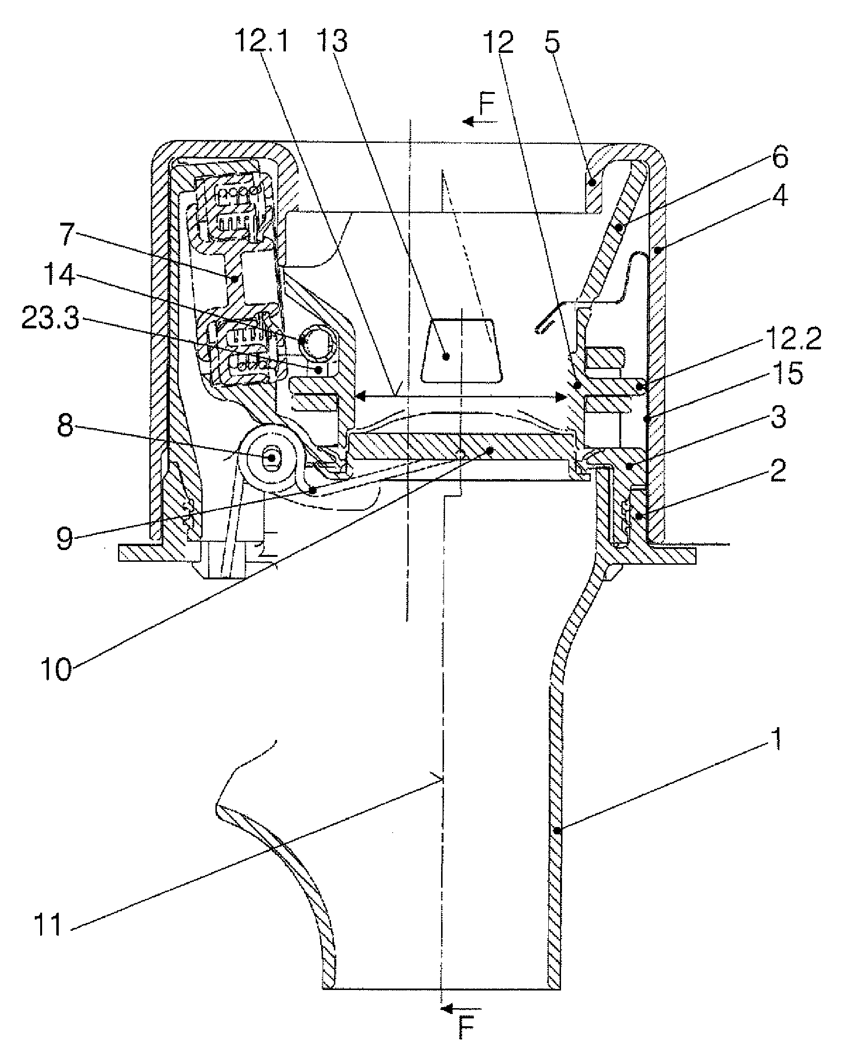
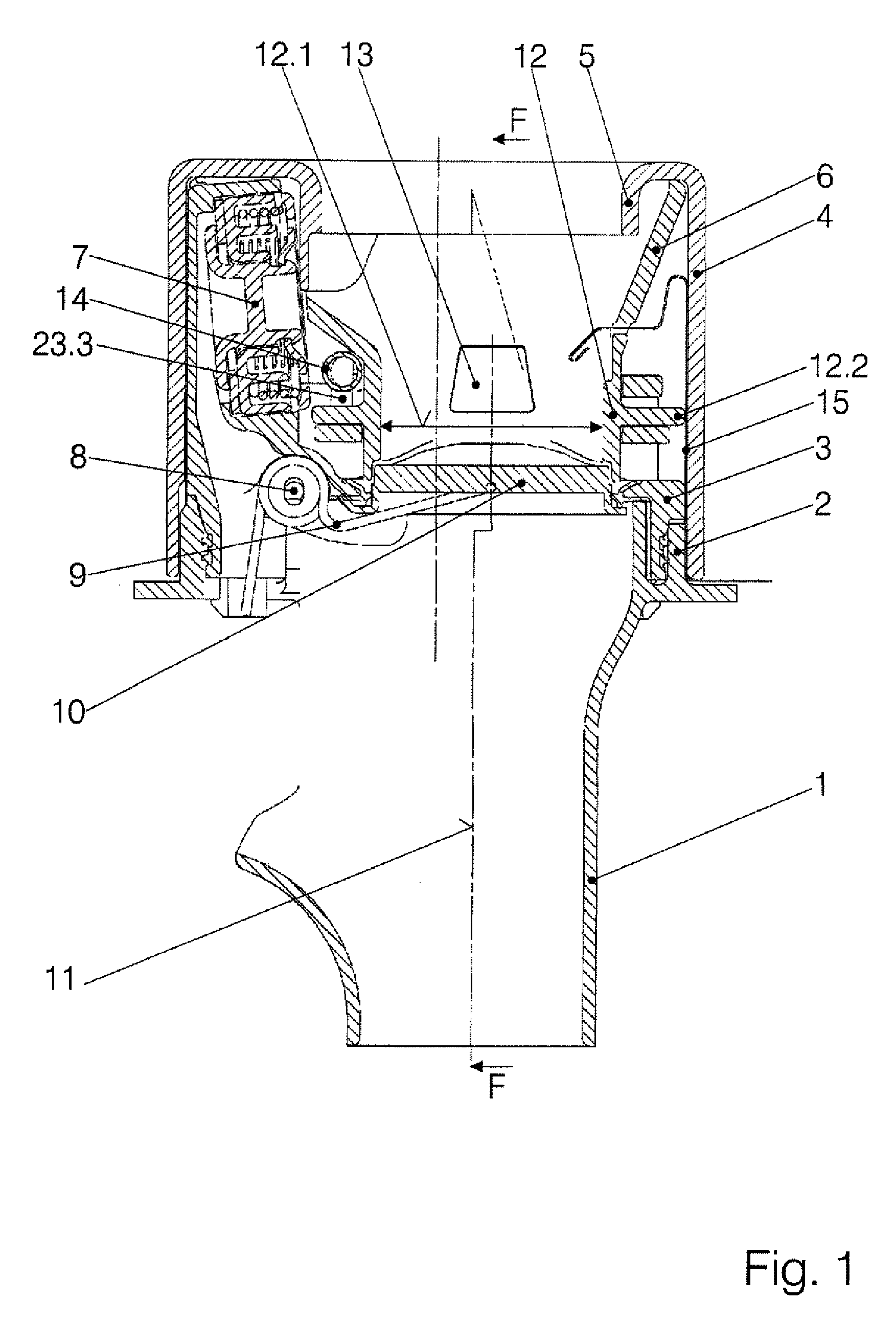
[0019]In FIG. 1, the support body is formed by a pipe piece 1 having a flange 2, a latch 3, an attachment 4 with a flanged edge 5, and an inlet funnel 6 which runs out downward into a hollow cylinder 12. The latch 3 holds a flap 10 which can be pivoted up counter to the force of a hairpin spring 9 about an axle 8, and laterally, a valve 7, for example an overpressure valve. Said latch 3 and the attachment 4 are fastened to the flange 2. The hollow cylinder 12 serves to guide a filler pipe (not illustrated) of a fueling nozzle. The filler pipe has the standard diameter for diesel fuel, which is greater than that of a filler pipe for unleaded gasoline. The latter is also referred to as an “incorrect” filler pipe. The hollow cylinder 12 has the diameter 12.1 which allows the “correct” filler pipe to pass through. Furthermore, the hollow cylinder 12 is surrounded by a flange 12.2 on which the device according to the invention for preventing incorrect fueling is arranged. The associated ...


PUM

PropertyMeasurementUnit
diameteraaaaaaaaaa
angleaaaaaaaaaa
guide lengthaaaaaaaaaa

Abstract

The filler neck of a fuel tank with an arrangement for preventing incorrect fueling has a rotatable ring and closing elements which are actuated by said ring, with a transmission device having the following features being arranged between the movable part and the rotatable ring:there are two slides which are situated opposite one another and which have run-on faces which face toward one another in the support body,the two slides are connected to one another by means of a rigid bar, which rigid bar is movably articulatedly connected with its first end to the first slide and with its second end to the second slide,the second end of the bar is a bolt which engages into a first slot of the second slide and into a second slot of the rotatable ring.

Description

BACKGROUND OF THE INVENTION[0001]The invention relates to the filler neck of a fuel tank with an arrangement for preventing incorrect fueling, composed of a neck body, at least one part which can be moved counter to a spring force by inserting the filler pipe of the correct diameter, a rotatable ring and closing elements which are actuated by said ring, with a transmission device being arranged between the movable part and the rotatable ring.[0002]In motor vehicles with a diesel engine, the risk of incorrect fueling is high because the diameter of the filler pipe of a fueling nozzle for unleaded gasoline is smaller than that of a fueling nozzle for diesel fuel. The correct diameter is therefore the larger diameter, and the following invention concerns very reliably preventing the insertion of a smaller filler pipe into a larger hole.[0003]It is known from EP 1 284 212 B1 for a tube piece which is movable in the longitudinal direction and which has a constriction at the tank side to ...

Claims


Application Information

Patent Timeline
Patent Type & Authority Applications(United States)
IPC IPC(8): B60K15/04
CPCB60K15/04B60K2015/0483Y10T137/86332
Inventor FEICHTINGER, STEFAN
Owner MAGNA STEYR FUEL SYST
Why Eureka
Try Eureka