Pillar construction for vehicle

Active Publication Date: 2008-10-02
MITSUBISHI MOTORS CORP +1
View PDF3 Cites 6 Cited by
  • Summary
  • Abstract
  • Description
  • Claims
  • Application Information

AI Technical Summary

Benefits of technology

[0006]An object of the invention is to provide a vehicle pillar which provides high rigidity and moreover, even though the vehicle pillar is formed by

Problems solved by technology

However, with such a construction in which the C pillar is divided into the upper member and the lower member, and the upper member and the lower member are joined together just by welding along the parting line which divides the C pillar in the way as described above, there has still remained a problem that the joined portion becomes rectilinear, and strength, in particular, rigidity with respect to the transverse direction of the vehicle or rigidity with respect to torsion cannot be obtained sufficiently.
In addition, aligning the joining portions is not easy, and when fitting portions formed respectively on the upper member and the lower member are brou

Method used


Image

  • Pillar construction for vehicle
  • Pillar construction for vehicle
  • Pillar construction for vehicle

Examples


Embodiment Construction

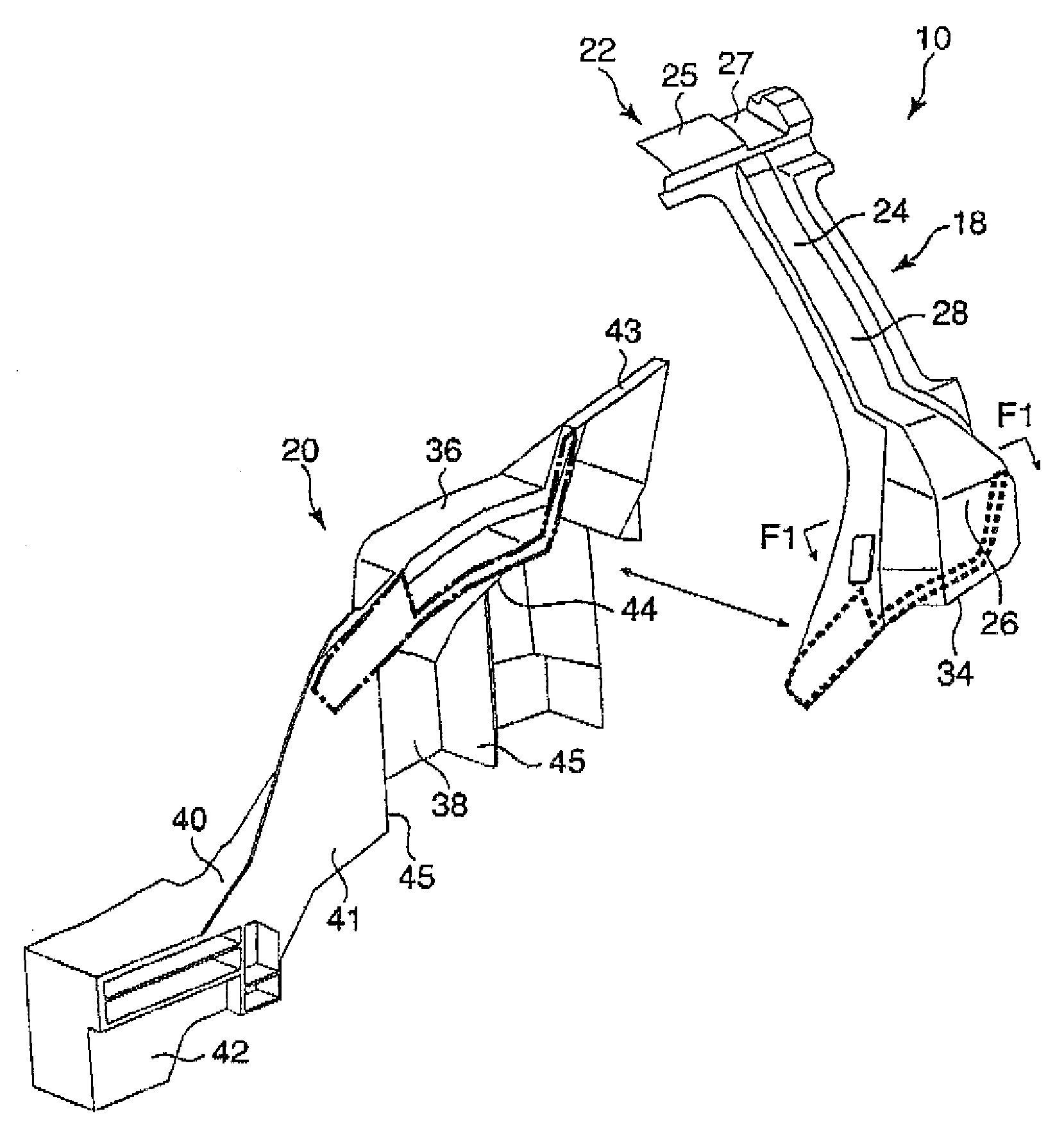
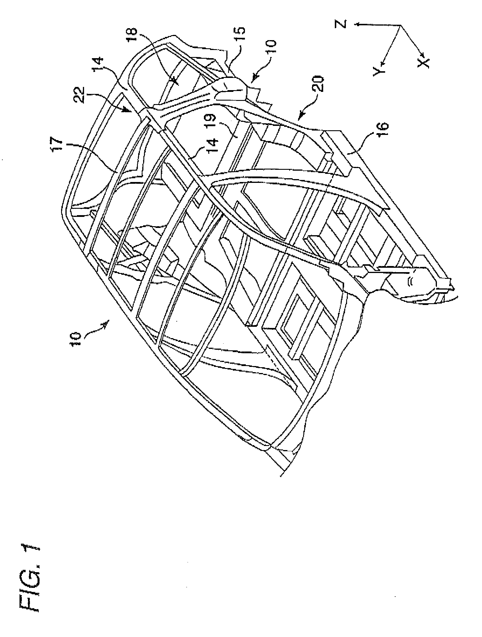
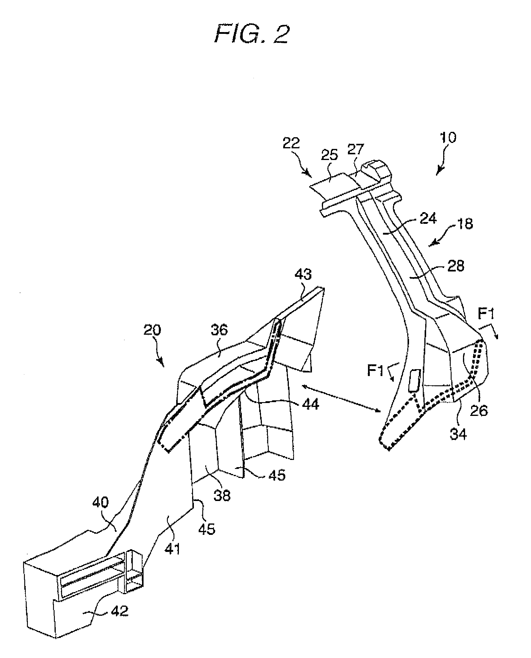
[0024]An embodiment of a vehicle pillar construction according to the invention will be described with reference to the drawings by taking a C pillar for example. FIG. 1 shows part of a body framework construction of a motor vehicle (a vehicle) which includes C pillars. In the following description, note that front (front side), rear (rear side) and left to right width or transverse directions are defined based on a traveling direction of a motor vehicle, and a direction which is directed towards a transverse center of the motor vehicle is defined as an inward direction (inside) whereas a direction expanding from the center of the motor vehicle towards the transverse direction as an outward direction (outside). In addition, a direction in which gravity acts is defined as a downward direction (lower side), and a direction opposite to the direction in which gravity acts as an upward direction (upper side). In the figures, arrows X, Y and Z denote three directions which are at right an...


PUM


Abstract

An upper member of a pillar has a substantially U-shaped cross section, and includes first side walls extending substantially in a transverse direction of the vehicle at least at a lower portion. The upper member includes a connecting plate at a lower end while keeping the U-shaped cross section. A lower member includes a mounting plate opposed to the connecting plate at a lower portion being lower than an upper end, and the lower member includes second side walls extending substantially in the transverse direction at both end portions of the mounting plate in a longitudinal direction of the vehicle. The connecting plate and the mounting plate are welded to each other in a state that the connecting plate and the mounting plate are in abutment with each other, and the first side walls and the second side walls or the first and second side walls and wall members attached to the first and second side walls, are joined to each other, and the upper member and the lower member are integrally fixed to each other.

Description

BACKGROUND OF THE INVENTION[0001]The present invention relates to a pillar construction for a vehicle which is made of a diecast aluminum alloy.[0002]In reducing the weight of a vehicle, it is considered to form members which make up a body of the vehicle using an aluminum alloy. In addition, when the body is made of aluminum alloy, it is considered to use a diecast aluminum alloy for a particular member which requires strength such as a c pillar (a rear pillar).[0003]On the other hand, the C pillar lies in the vicinity of a rear axle of the vehicle and is a member which is formed into a vertically long and complex shape in such a way that an upper portion is connected to a side roof rail and a lower portion extends as down as a rear suspension cross-member or a side sill. Due to this, in forming a C pillar of diecast aluminum alloy, it is considered that a C pillar is divided into an upper member and a lower member in the vicinity of substantially a vertical center of the C pillar,...

Claims


Application Information

Patent Timeline
IPC IPC(8): B60R27/00B60R99/00
CPCB62D25/04
Inventor NAKAMURA, TAKUONAKAGAWA, HAYAMIYANASE, JUNICHISEINO, HIROYUKIITO, HIDEKIFUJII, KOJIYANAGIMOTO, SETOSHIONODERA, MASATOAMANO, FUMIYA
Owner MITSUBISHI MOTORS CORP
Why Eureka
Try Eureka