Power supply unit for use with an aircraft electrical system

a technology for aircraft electrical systems and power supply units, applied in emergency power supply arrangements, electric devices, transportation and packaging, etc., can solve problems such as the sudden shutdown of aircraft electronics, the interruption of electrical power supplied to the aircraft electrical system, and the reset of aircraft electronics

Active Publication Date: 2008-10-02
CHAMPION AEROSPACE LLC +1
View PDF4 Cites 23 Cited by
  • Summary
  • Abstract
  • Description
  • Claims
  • Application Information

AI Technical Summary

Benefits of technology

[0006]In accordance with another aspect of the invention, there is provided a power supply unit for use with an aircraft power bus in which voltage differences between two nodes located at opposite ends of an impedance are used to control a switch that controls the supply of power from the unit. The power supply includes a connection circuit and energy storage circuit. The connection circuit has positive and negative input terminals for connecting to two corresponding terminals of the aircraft power bus. The energy storage circuit is electrically connected to the connection circuit. The connection circuit provides separate charging and discharging paths between the input terminals and the energy storage circuit. The connection circuit includes an impedance in the charging path and a switch in the discharge path. By monitoring voltages differences between two nodes located at opposite ends of the impedance, the power supply unit can control operation of said switch to either enable or inhibit the supply of power from the unit to the aircraft bus.

Problems solved by technology

In this arrangement, when the contactor switches between the various power sources there is a temporary interruption in the electrical power supplied to the aircraft electrical system.
This temporary interruption, which usually only lasts a few milliseconds to several hundred milliseconds, can cause some of the aircraft's electronics to turn off, reset, and / or erase information that has already been programmed, to name but a few ramifications.

Method used


Image

  • Power supply unit for use with an aircraft electrical system
  • Power supply unit for use with an aircraft electrical system
  • Power supply unit for use with an aircraft electrical system

Examples


Embodiment Construction

)

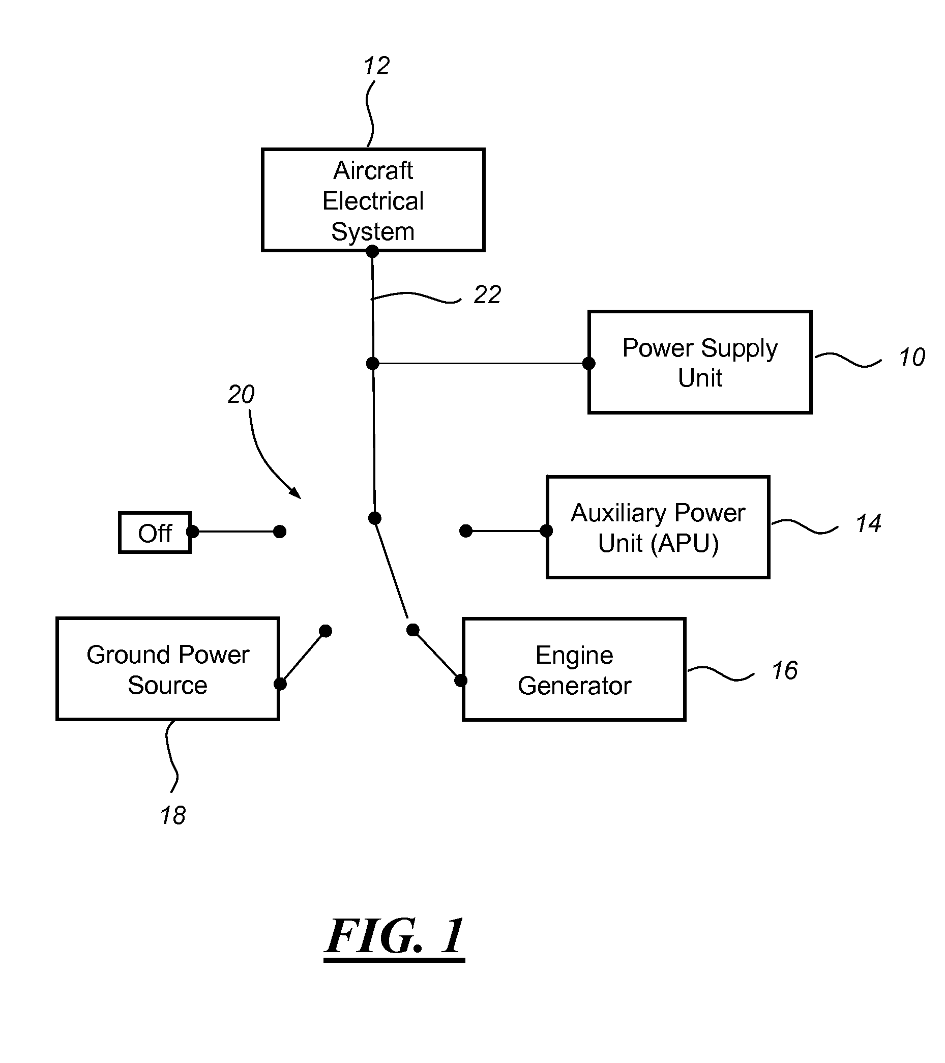
[0011]FIG. 1 schematically shows one example of an application that can use the uninterruptible power supply unit 10 described herein, and generally includes an aircraft electrical system 12 connected to a variety of electrical power sources 14-18 via a switching device or contactor 20. These sources include an APU 14, engine generator(s) 16, and ground power source 18. Contactor 20, which can either be a manually or automatically operated component, is schematically shown here as a four-position switch, but it could certainly be provided according to one of a number of different embodiments known in the art. Although the following description is provided in the context of a fixed-wing aircraft application, it should be appreciated that it is possible for power supply unit 10 to be used in a variety of other applications, such as those involving rotary-wing aircraft, spacecraft, etc.

[0012]According to this particular example, contactor 20 provides aircraft electrical system 12 with...


PUM


Abstract

A power supply unit that provides uninterrupted power to an aircraft power bus during switchovers of the aircraft bus from one power source to another. The power supply unit includes circuitry to distinguish between loss of bus power due to switchovers between power sources and loss of bus power due to shutdown of the aircraft. The power supply unit includes a low voltage lockout circuit to interrupt the supply of power when the aircraft bus voltage falls below a minimum value.

Description

CROSS-REFERENCE TO RELATED APPLICATION[0001]This application claims the priority of U.S. Provisional Application No. 60 / 908,148, filed Mar. 26, 2007, the entire contents of which are hereby incorporated by reference.TECHNICAL FIELD[0002]This invention relates generally to power supplies and, more specifically, to power supplies used onboard aircrafts to provide uninterrupted power during temporary power disruptions.BACKGROUND OF THE INVENTION[0003]Aircraft electrical power typically comes from different sources depending on whether the aircraft is on the ground, preparing for takeoff, or in flight. For instance, when the aircraft is on the ground and parked at a terminal, electrical power is usually provided via a removable power cable that connects the aircraft to a ground power source. This ground power source typically provides the aircraft with AC power that is subsequently converted to DC power by rectifying equipment located on the aircraft. As the aircraft prepares for takeof...

Claims


Application Information

Patent Timeline
Patent Type & Authority Applications(United States)
IPC IPC(8): B60L1/00H02H3/00
CPCH02J9/06H02J2310/44H02J9/061
Inventor COTTINGHAM, JOHN D.DAVIS, SCOTT A.BERLLNER, JAMES R.LOCKMILLER, ROBERT A.
Owner CHAMPION AEROSPACE LLC
Why Eureka
Try Eureka