Modular combined transmission suitable for more gears
What is AI technical title?
AI technical title is built by Patsnap AI team. It summarizes the technical point description of the patent document.
A modular, transmission technology, applied in the field of gear transmissions, can solve the problems of complex structure and difficult layout of gear transmissions
Active Publication Date: 2017-05-24
SHANXI GUOLI INFORMATION TECH
View PDF4 Cites 2 Cited by
Summary
Abstract
Description
Claims
Application Information
AI Technical Summary
This helps you quickly interpret patents by identifying the three key elements:
Problems solved by technology
Method used
Benefits of technology
Problems solved by technology
[0005]
In order to solve the problems of complex structure and difficult layout of existing gear transmissions, the present invention provides a modular combination transmission suitable for more gears
Method used
Image
Click on the blue label to locate the original text in one second.
Reading with bidirectional positioning of images and text.
Examples
Embodiment 1
[0133] Such as Figure 5c As shown, the B clutch is a friction plate type helical surface external compression overrunning clutch, including a clutch limit device G27, a fixed assembly G22, a rotating assembly G21, a self-locking / overrunning control device and an additional clutch control device arranged on the same rotation axis.
[0134] The fixed assembly G22 includes a first force transmission drum G221 and a plurality of first friction plates G222 arranged on the first force transmission drum G221, the first friction plates G222 can slide relative to the first force transmission drum G221 in the axial direction, The first friction plate G222 and the first force transmission drum G221 rotate synchronously along the circumferential direction.
[0135] The rotating assembly G21 includes a second force transmission hub G211 and a plurality of second friction plates G212 arranged outside the second force transmission hub G211, the second friction plates G212 can slide relative...
Embodiment 2
[0148] Such as Figure 5d As shown, the B clutch is a friction disc type helical surface compression overrunning clutch, including a clutch limit device G27 set on the same rotation axis, a fixed component G22, a rotating component G21, a self-locking / overrunning control device and an additional clutch control device .
[0149] The fixed assembly G22 includes a first force transmission drum G221 and a plurality of first friction plates G222 arranged on the first force transmission drum G221, the first friction plates G222 can slide relative to the first force transmission drum G221 in the axial direction, The first friction plate G222 and the first force transmission drum G221 rotate synchronously along the circumferential direction.
[0150] The rotating assembly G21 includes a second force transmission hub G211 and a plurality of second friction plates G212 arranged outside the second force transmission hub G211, the second friction plates G212 can slide relative to the sec...
Embodiment 3
[0166] The B clutch is a friction plate type helical surface external compression overrunning clutch, which is similar to the structure of the B clutch in Embodiment 1, the difference is:
[0168] The second helicoid coupler G24 is fixedly connected with the second force transmission hub G211; the second helicoid coupler G24 is located in the space formed by the second force transmission hub G211, the supporting body and the first helicoid coupler G23.
[0169] The supporting body and the first force transmission drum G221 serve as two force transmission ends of the overrunning clutch respectively.
PUM
Abstract
The invention provides a modular combined transmission suitable for more gears. The modular combined transmission comprises a first gearshift module; the first gearshift module comprises an input shaft, an output shaft and a three-speed device; the three-speed device comprises a gear mechanism and clutches C, B and D; the gear mechanism comprises an input gear, an intermediate shaft gear assembly, a transition gear assembly, an output gear and a gear retainerassembly composed of a front retainer, a middle retainer and a rear retainer; the middle retainer is provided with a central output shaft serving as a second output of the gear mechanism; the outside of the central output shaft is sleeved with a central output shaft tube serving as a first output of the gear mechanism; and the first and final gears of the intermediate shaft gear assembly are respectively meshed with the input gear and the output gear, and the rest gears are meshed with a transition gear. A driving assembly and a driven assembly of the clutch C are respectively fixedly connected with the input shaft and the gear retainer assembly; a rotating assembly and a fixed assembly of the clutch B are respectively fixedly connected with the gear retainer assembly and a shell; and the clutch D is used for switching the output of the gear mechanism. One of the three clutches is selected to be locked. The modular combined transmission is simple in structure and easy to lay out.
Description
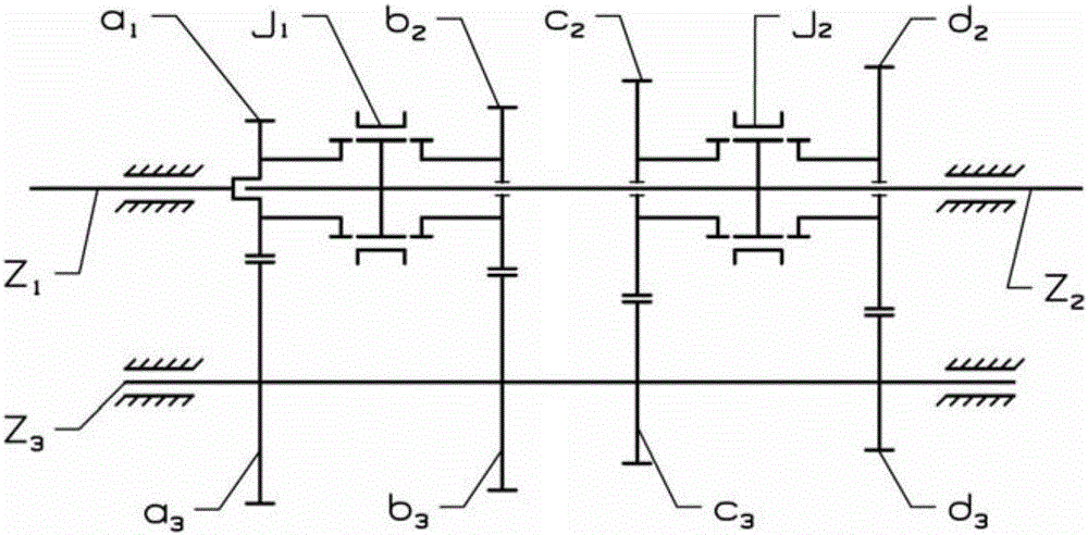
technical field [0001] The present invention relates to a gear transmission applied to a vehicle, in particular to a modular combined transmission with more gears. Background technique [0002] There are two types of existing gear transmissions: fixed shaft type and planetary gear type. [0003] Such as figure 1 Shown is a schematic diagram of a fixed shaft gear transmission with three fixed gear shafts: the first shaft (input shaft) Z 1 , the second axis (output axis) Z 2 and intermediate axis Z 3 , the first axis Z 1 and the second axis Z 2 They are coaxially arranged side by side with a distance apart in the axial direction and can be rotated relative to each other. The intermediate axis Z 3 with the first axis Z 1 and the second axis Z 2 Arranged in parallel. First axis Z 1 1 gear a is mounted on the body 1 , both rotate synchronously; the second axis Z 2 3 gears b 2 、c 2 、d 2 , these three gears are sleeved on the second axis Z 2 on, and with respect to ...
Claims
Application Information
Patent Timeline
Application Date:The date an application was filed.
Publication Date:The date a patent or application was officially published.
First Publication Date:The earliest publication date of a patent with the same application number.
Issue Date:Publication date of the patent grant document.
PCT Entry Date:The Entry date of PCT National Phase.
Estimated Expiry Date:The statutory expiry date of a patent right according to the Patent Law, and it is the longest term of protection that the patent right can achieve without the termination of the patent right due to other reasons(Term extension factor has been taken into account ).
Invalid Date:Actual expiry date is based on effective date or publication date of legal transaction data of invalid patent.

