Segmented permanent magnet rotor for high speed synchronous machines

a permanent magnet rotor and high-speed synchronous technology, which is applied in the direction of dynamo-electric machines, magnetic circuit rotating parts, magnetic circuit shape/form/construction, etc., can solve problems such as thermal overloading and failure of synchronous machines, and achieve the effects of reducing eddy current losses

Inactive Publication Date: 2008-10-02
HAMILTON SUNDSTRAND CORP
View PDF10 Cites 50 Cited by
  • Summary
  • Abstract
  • Description
  • Claims
  • Application Information

AI Technical Summary

Benefits of technology

[0005]A permanent-magnet rotor has an axially segmented containment sleeve and axially segmented permanent magnets that reduce eddy-current losses in the permanent-magnet rotor. The containment sleeve is axially segmented by one or more circumferential grooves located on the outer periphery of the containment sleeve that disrupt an axial current path around the outer periphery of the containment sleeve, thereby reducing eddy current losses (less effective would be grooves...

Problems solved by technology

If not managed properly, high eddy-current losses may result in failure of the synchronous machine.
In particular, hig...

Method used


Image

  • Segmented permanent magnet rotor for high speed synchronous machines
  • Segmented permanent magnet rotor for high speed synchronous machines
  • Segmented permanent magnet rotor for high speed synchronous machines

Examples


Embodiment Construction

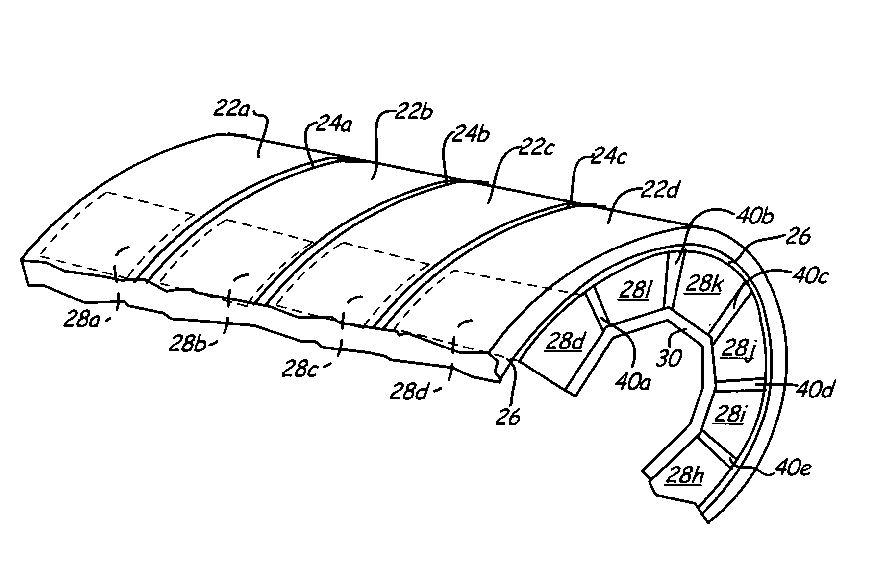
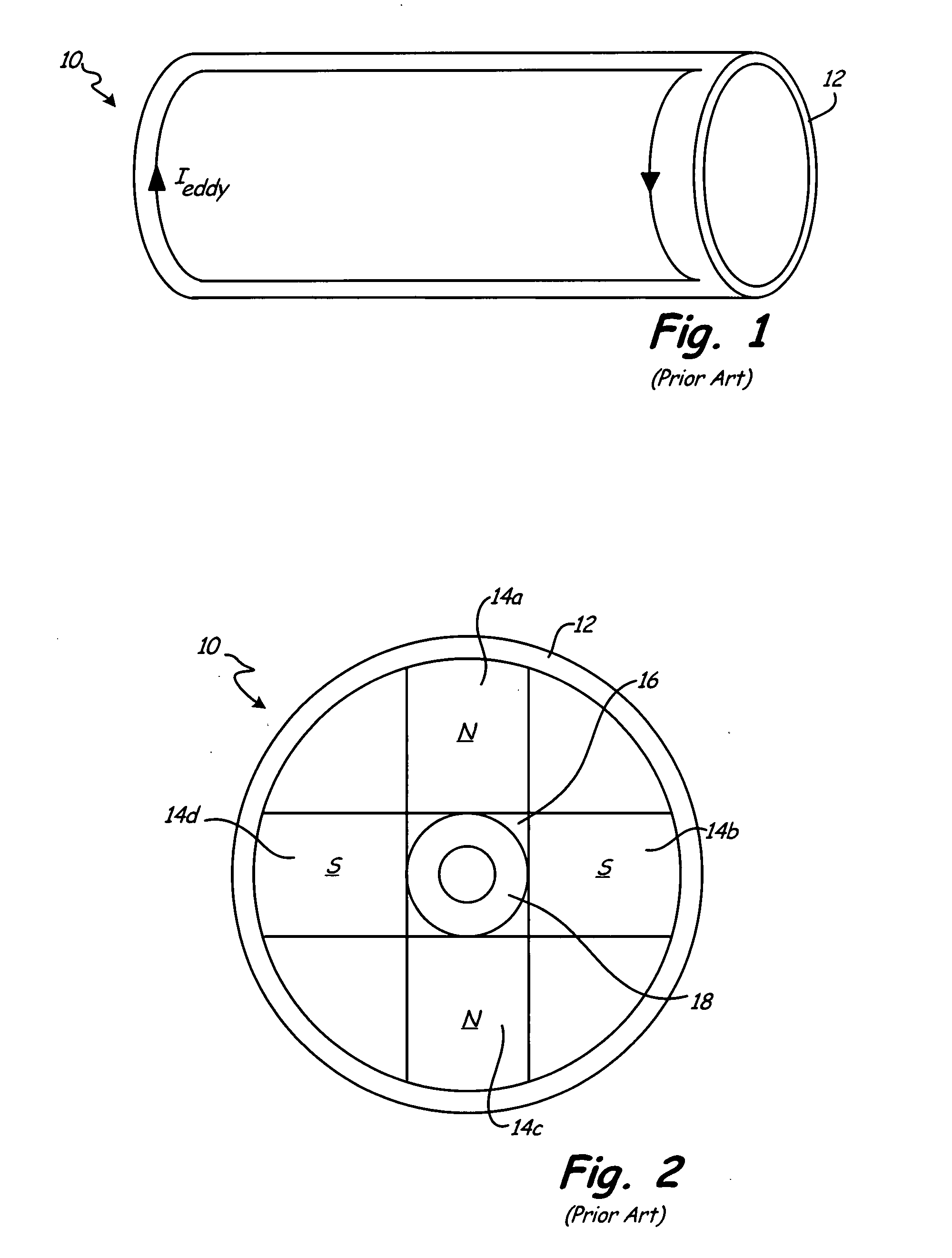
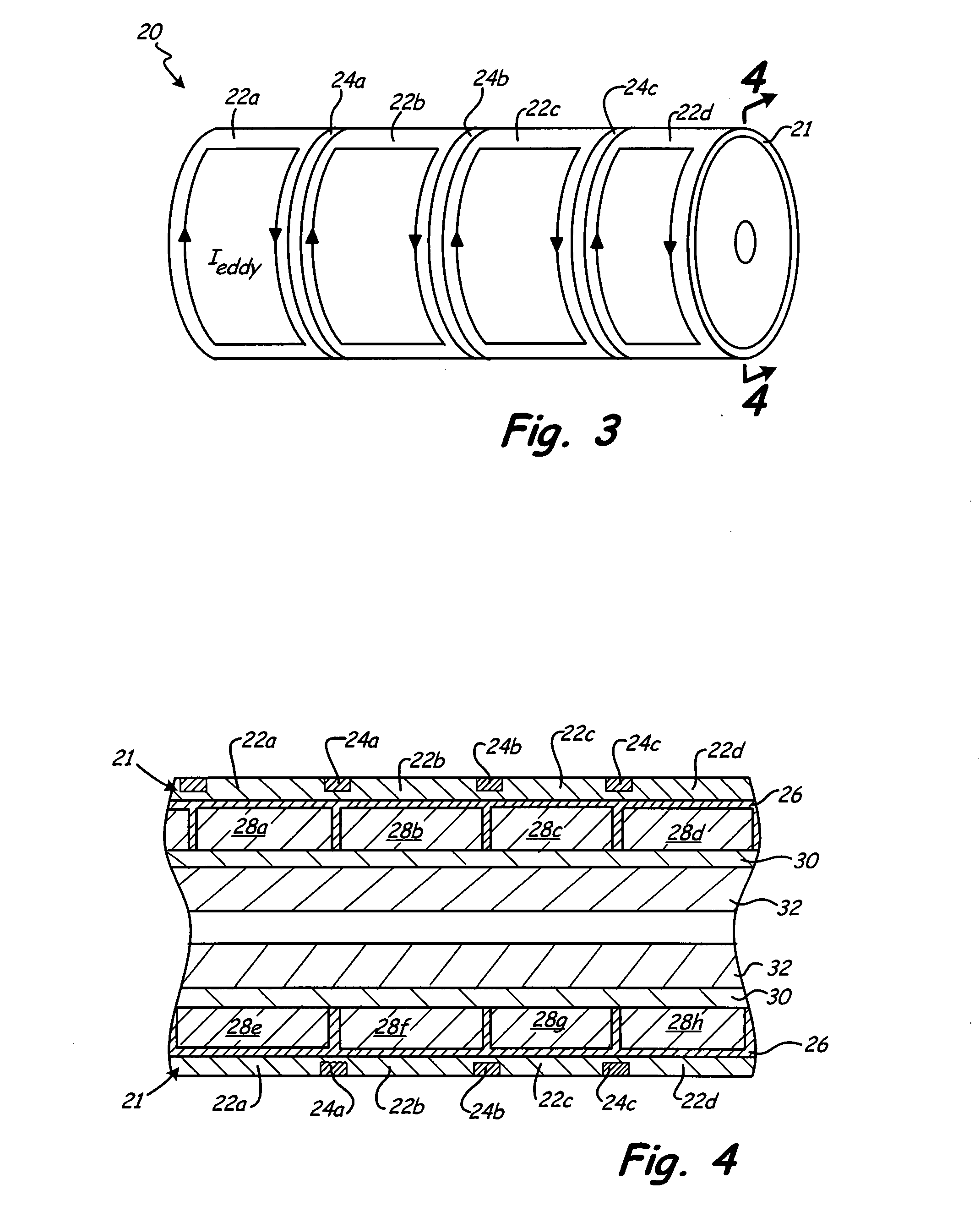
[0012]FIGS. 1 and 2 illustrate a prior art embodiment of a permanent-magnet rotor. FIG. 1 is a perspective view of the permanent-magnet rotor, and FIG. 2 is an end view of the same permanent-magnet rotor.

[0013]As shown in FIG. 2, permanent-magnet rotor 10 includes containment sleeve 12, permanent magnets 14a, 14b, 14c, and 14d (collectively, permanent magnets 14), magnetic steel hub 16, and rotor core 18.

[0014]Permanent-magnet rotor 10 may be used in high-speed permanent-magnet machines, such as permanent-magnet generators and permanent-magnet motors. Containment sleeve 12 is located on the outer periphery of permanent magnets 14, and is used to contain permanent magnets 14 in the radial direction. In particular, containment sleeves are used in high-speed applications, in which centripetal force generated by the rotation of permanent-magnet rotor 10 causes permanent magnets 14 to pull away from magnetic steel hub 16. Therefore, in high-speed applications, containment sleeve 12 serve...


PUM


Abstract

The segmented permanent-magnet rotor for high-speed synchronous machines reduces eddy-current losses by axially segmenting the containment sleeve and the permanent magnets. The axial segmentation of the containment sleeve includes forming grooves circumferentially around the outer surface of the containment sleeve. The circumferential grooves disrupt the generation of eddy currents on the outer surface of the containment sleeve and therefore reduce eddy-current losses in the containment sleeve. Axial segmentation of the permanent magnets also disrupts eddy current formation, thereby reducing eddy current losses in the permanent magnets. In addition, the presence of an electrically insulating layer between the containment sleeve and the permanent magnets reduces eddy current migration from the containment sleeve to the permanent magnets, and therefore provides additional reduction of eddy-current losses.

Description

BACKGROUND OF THE INVENTION[0001]The present invention relates to high-speed synchronous machines, and more specifically to high-speed synchronous machines having segmented rotor sleeves and permanent magnets (PMs).[0002]Synchronous machines, a variety of which is the surface mount permanent magnet (SMPM) machine, have become increasingly popular in a variety of applications. For instance, SMPM machines may be used in conjunction with high-speed turbo machines commonly found in both aerospace and ground applications.[0003]The permanent magnets employed in the rotor portion of a synchronous machine may be constrained in the radial direction by a containment band, or sleeve. Containment sleeves are typically used in high-speed applications to prevent centripetal forces from separating the permanent magnets from a magnetic rotor hub. Although in some embodiments, the containment sleeve may be formed using a non-conductive composite material, a number of applications require an interfer...

Claims


Application Information

Patent Timeline
IPC IPC(8): H02K1/27
CPCH02K1/278
Inventor SABAN, DANIEL M.VANEK, LAURENCE D.
Owner HAMILTON SUNDSTRAND CORP
Why Eureka
Try Eureka