
Fully-charged battery capacity detection method

Active Publication Date: 2008-10-02
SANYO ELECTRIC CO LTD
View PDF3 Cites 45 Cited by
  • Summary
  • Abstract
  • Description
  • Claims
  • Application Information

AI Technical Summary

Benefits of technology

[0008]The present invention has been developed for solving the disadvantages. It is an important object of the present invention is to provide a method capable of accurately detecting the fully-charged capacity of a battery without bringing the battery to the fully-charged state or the fully-discharged state.
[0021]In this fully-charged battery capacity detection method, since the first and second remaining capacities (SOC1 [%], SOC2 [%]) of the battery are determined based on the first and second open-circuit voltages (VOCV1, VOCV2), respectively, by the stored function or table, the remaining capacities (SOC [%]) are accurately detected based on the open-circuit voltages (VOCV), and it is possible to accurately detect the fully-charged capacity.

Problems solved by technology

However, since these methods estimate the reduction degree of the fully-charged capacity based on the accumulated charging capacity amount, or based on the storage temperature and the remaining capacity, there is a disadvantage in that it is difficult to constantly accurately detect the fully-charged capacity of the battery.
The reason is that the deterioration of batteries complicatedly varies with various external conditions.

Method used


Image

  • Fully-charged battery capacity detection method
  • Fully-charged battery capacity detection method
  • Fully-charged battery capacity detection method

Examples


Embodiment Construction

)

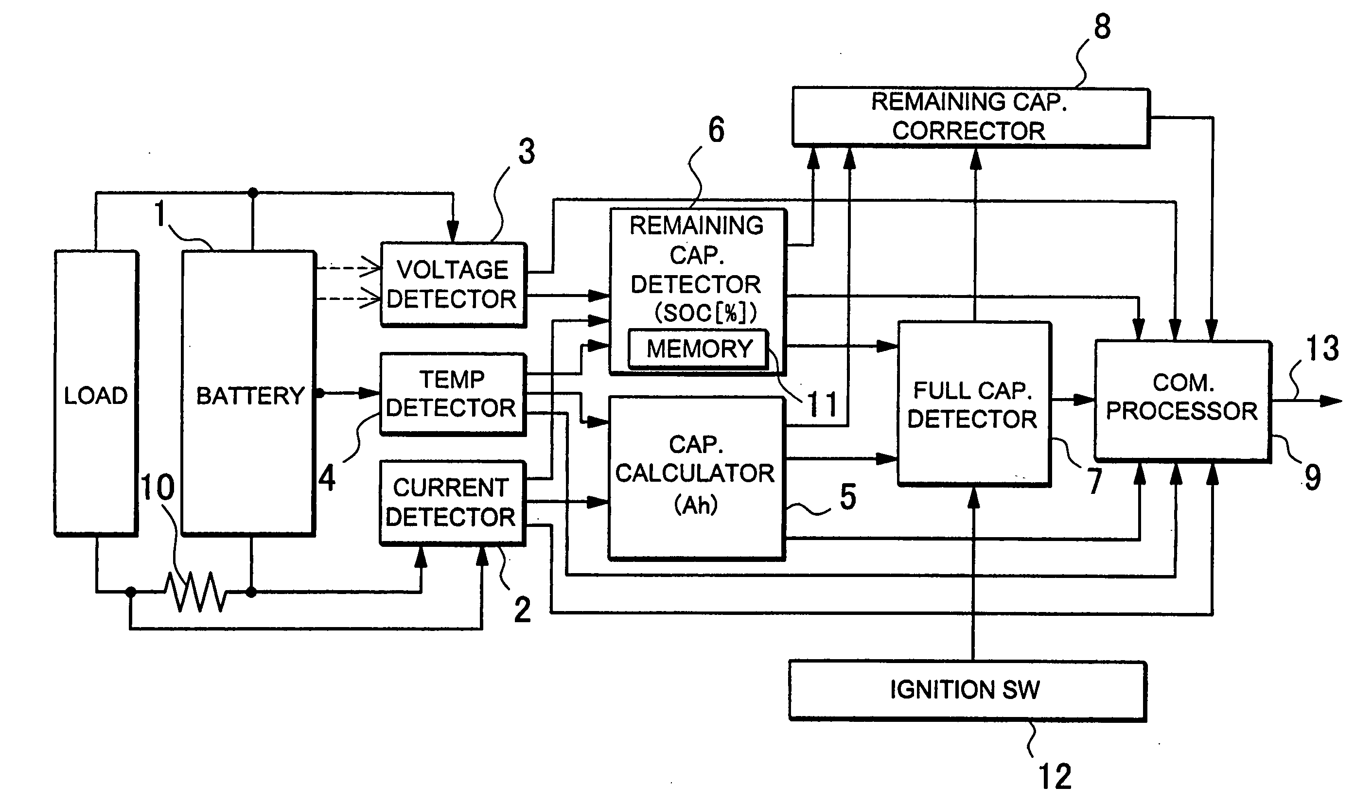
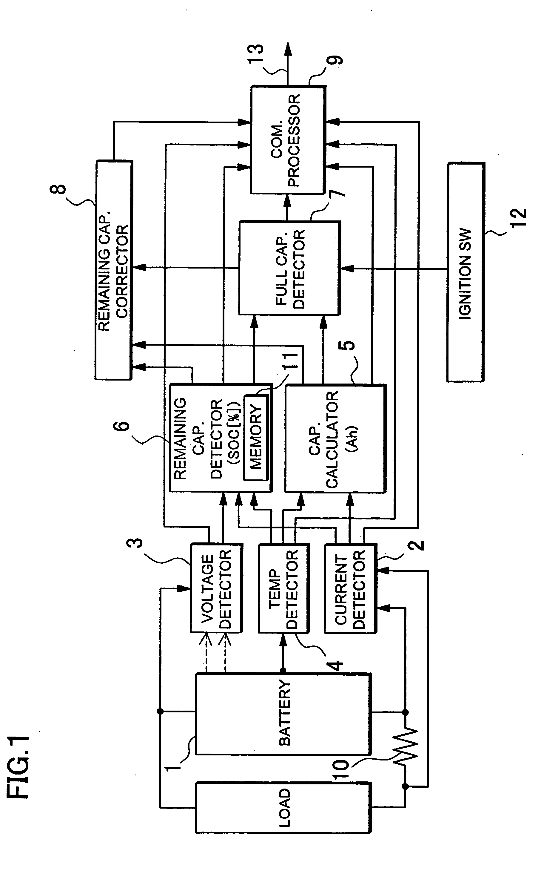
[0031]FIG. 1 is a circuit diagram of a vehicle power supply device that is used in a fully-charged battery capacity detection method according to the present invention. This power supply device includes a rechargeable battery 1, a current detection portion 2, a voltage detection portion 3, a temperature detection portion 4, a capacity calculation portion 5, a remaining capacity detection portion 6, a fully-charged capacity detection portion 7, a remaining capacity correction circuit 8, and a communication processing portion 9. The current detection portion 2 detects the charging / discharging currents of the battery 1. The voltage detection portion 3 detects the voltage of the battery 1. The temperature detection portion 4 detects the temperature of the battery 1. The capacity calculation portion 5 calculates the output signals of the current detection portion 2 and integrates the charging / discharging currents of the battery 1 to detect the capacity (Ah) of the battery 1. The remaini...


PUM


Abstract

A fully-charged battery capacity detection method includes a capacity variation detection step, an open-circuit voltage detection step, a remaining capacity determination step, a remaining capacity variation rate calculation step, and a fully-charged capacity calculation step. The capacity variation detection step calculates a capacity variation value (δAh) of a battery between first detection timing and second detection timing. The open-circuit voltage detection step detects first and second open-circuit voltages (VOCV1, VOCV2) of the battery at the first and second detection timing, respectively. The remaining capacity determination step determines first and second remaining capacities (SOC1 [%], SOC2 [%]) of the battery based on the first and second open voltages (VOCV1, VOCV2), respectively. The remaining capacity variation rate calculation step calculates a remaining capacity variation rate (δS [%]) based on the difference between the first and second remaining capacities (SOC1 [%], SOC2 [%]). The fully-charged capacity calculation step calculates a fully-charged capacity (Ahf) of the battery based on the remaining capacity variation rate (δS [%]) and the capacity change value (δAh).

Description

BACKGROUND OF THE INVENTION[0001]1. Field of the Invention[0002]The present invention relates to a method for detecting a fully-charged battery capacity, which decreases with increasing the number of charging / discharging operation cycles.[0003]2. Description of the Related Art[0004]The fully-charged capacity (Ahf) of a battery decreases with time and with increasing the number of charging / discharging operation cycles. The fully-charged / discharged capacity (Ahf) is the capacity of a battery that can be discharged from a fully charged state to a fully-discharged state. Batteries remarkably deteriorate when over-charged or over-discharged. For this reason, in order to suppress deterioration, a battery is used so that the capacity of the battery falls within a range around a predetermined remaining capacity (SOC [%]) relative to the fully-charged capacity (Ahf). Accordingly, it is important to accurately detect the fully-charged capacity (Ahf), which decreases with time. If the detectio...

Claims


Application Information

Patent Timeline
IPC IPC(8): H02J7/00
CPCG01R31/361G01R31/3828
Inventor TAMEZANE, SHIGETO
Owner SANYO ELECTRIC CO LTD
Learn More