
Liquid discharging head and liquid discharging apparatus

a liquid discharging head and liquid discharging technology, applied in printing and other directions, can solve the problems of increasing the size of the pump, difficulty in sufficiently removing the bubbles, etc., and achieve the effect of convenient movement, smooth removal and convenient movemen

Inactive Publication Date: 2008-10-02
SONY CORP
View PDF1 Cites 8 Cited by
  • Summary
  • Abstract
  • Description
  • Claims
  • Application Information

AI Technical Summary

Benefits of technology

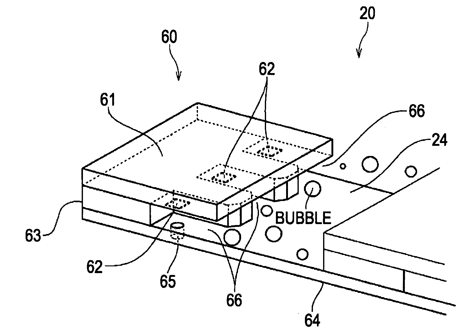
[0012]Unfortunately, in the technique disclosed in the above-described publication, the bubbles are sometimes adsorbed on the ceiling surface of the common passage, and stay thereat. This makes it difficult to sufficiently remove the bubbles. Further, if the inclination of the ceiling surface is increased to reliably move the bubbles, the capacity of the common passage increases. As a result, the size of the pump increases.
[0013]Accordingly, it is desirable to reliably move bubbles even with a low-rate pump and to smoothly remove bubbles from liquid (ink) in a common passage.
[0016]In the above embodiments, the common passage member includes the inlet through liquid is supplied to the common passage, and the outlet through which the liquid is ejected from the common passage. The ceiling surface of the common passage has the groove extending from the inlet toward the outlet. For this reason, even when bubbles contained in the liquid in the common passage are brought into contact with the ceiling surface by the buoyancy, since the ceiling surface is kept in a water retention state by the groove, it does not adsorb the bubbles. This allows the bubbles to move easily.
[0017]According to the embodiments of the present invention, since the ceiling surface of the common passage is kept in a water retention state by the groove and bubbles are not adsorbed to the ceiling surface. Therefore, bubbles contained in the liquid can easily move even when they are brought into contact with the ceiling surface by the buoyancy. For this reason, even when a low-rate pump is used, the bubbles reliably move, and can be smoothly removed from the liquid in the common passage.

Problems solved by technology

Unfortunately, in the technique disclosed in the above-described publication, the bubbles are sometimes adsorbed on the ceiling surface of the common passage, and stay thereat.
This makes it difficult to sufficiently remove the bubbles.
As a result, the size of the pump increases.

Method used


Image

  • Liquid discharging head and liquid discharging apparatus
  • Liquid discharging head and liquid discharging apparatus
  • Liquid discharging head and liquid discharging apparatus

Examples


first embodiment

[0062]FIGS. 5A and 5B are cross-sectional views of the line head 10s shown in FIG. 4 according to a first embodiment.

[0063]As shown in FIGS. 5A and 5B, the line head 10 includes a head chip 60, a nozzle sheet 64, and a buffer tank 21. A common passage 24 is defined by the buffer tank 21. Ink is supplied into the common passage 24 through an inlet 22, and ink containing bubbles is ejected through an outlet 23. A ceiling surface of the common passage 24 has a plurality of (four on each of the right and left sides) grooves 25 extending from the inlet 22 toward the outlet 23.

[0064]Bubbles produced in the common passage 24 rise because of buoyancy. Although the bubbles are going to stick on the ceiling surface of the common passage 24, the ceiling surface has a plurality of grooves 25, and ink is retained in the grooves 25 by capillary action. For this reason, even if the bubbles attempt to stick on the ceiling surface of the common passage 24, the sticking force of the bubbles is seriou...

second embodiment

[0067]FIG. 6 is a cross-sectional view of a line head 30 according to a second embodiment.

[0068]As shown in FIG. 6, a buffer tank 31 in the line head 30 according to the second embodiment includes two partition walls 36a and 36b. By the two partition walls 36a and 36b, a common passage 34 is divided into three passage chambers 34a, 34b, and 34c between an inlet 32 and an outlet 33. The passage chambers 34a, 34b, and 34c communicate with one another on the upper sides of the partition walls 36a and 36b. A head chip 60 is provided in each of the three passage chambers 34a, 34b, and 34c.

[0069]On ceiling surfaces of the passage chambers 34a, 34b, and 34c of the common passage 34, a plurality of grooves 35a, 35b, and 35c extend from the inlet 32 toward the outlet 33. For this reason, when ink is supplied (circulated) from the inlet 32, a bubble in the passage chamber 34a moves along the groove 35a with the flow of the ink, and enters the next passage chamber 34 beyond the partition wall...

third embodiment

[0072]FIG. 7 is a cross-sectional view of a line head 40 according to a third embodiment of the present invention.

[0073]As shown in FIG. 7, a buffer tank 41 in the line head 40 according to the third embodiment includes two partition walls 46a and 46b, similarly to the line head 30 of the second embodiment shown in FIG. 6. By the two partition walls 46a and 46b, a common passage44 is divided into three passage chambers 44a, 44b, and 44c between an inlet 42 and an outlet 43. The passage chambers 4a, 44b, and 44c communicate with one another on the upper sides of the partition walls 46a and 46b.

[0074]On ceiling surfaces of the passage chambers 44a, 44b, and 44c of the common passage 44, a plurality of grooves 45a, 45b, and 45c extend from the inlet 42 toward the outlet 43. The grooves 45a, 45b, and 45c are similarly inclined upward from the inlet 42 toward the outlet 43.

[0075]In the line head 40, the grooves 45a, 45b, and 45c are thus inclined upward from the inlet 42 toward the outl...


PUM


Abstract

A liquid discharging head includes a head chip including a plurality of energy generating elements configured to discharge liquid and liquid chambers provided around the corresponding energy generating elements, and a common passage member configured to define a common passage communicating with all the liquid chambers in the head chip. the liquid is discharged from the liquid chambers by driving the energy generating elements so as to apply a discharging force to the liquid. The common passage member includes an inlet through which the liquid is supplied to the common passage, and an outlet through which the liquid is ejected from the common passage. The common passage includes a ceiling surface having a groove extending from the inlet toward the outlet.

Description

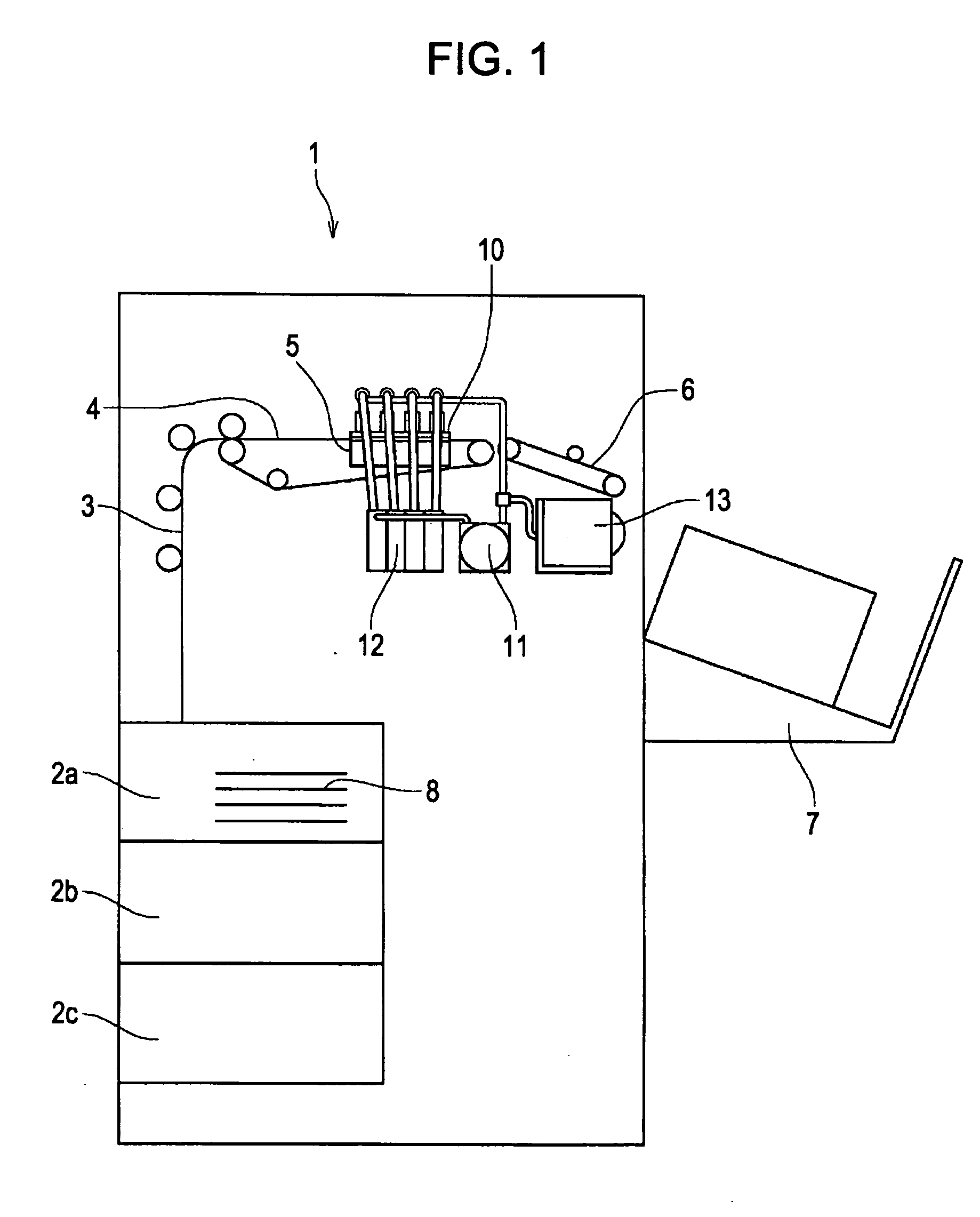
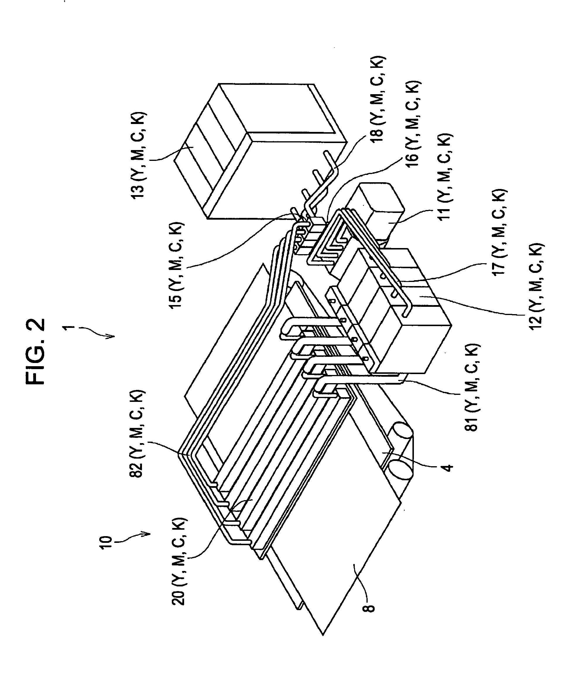
CROSS REFERENCES TO RELATED APPLICATIONS[0001]The present invention contains subject matter related to Japanese Patent Application JP 2007-090861 filed in the Japanese Patent Office on Mar. 30, 2007, the entire contents of which are incorporated herein by reference.BACKGROUND OF THE INVENTION[0002]1. Field of the Invention[0003]The present invention relates to a liquid discharging head and a liquid discharging apparatus which include a common passage member that defines a common passage communicating with all liquid chambers in a head chip and which discharge liquid from the liquid chambers by driving energy generating elements in the head chip so as to apply a discharging force to the liquid in the liquid chambers. More particularly, the present invention relates to a technique of smoothly removing bubbles from the liquid in the common passage.[0004]2. Description of the Related Art[0005]In an inkjet printer as an example of a liquid discharging apparatus, a recording sheet is conv...

Claims


Application Information

Patent Timeline
Patent Type & Authority Applications(United States)
IPC IPC(8): B41J2/19B41J2/05
CPCB41J2/515B41J2/175B41J2/19B41J2/045B41J2/01
Inventor HIRASHIMA, SHIGEYOSHIHARADA, AKIKOYAMAGUCHI, SHUNJI
Owner SONY CORP
Learn More