
Wireless Communication Apparatus

a communication apparatus and wireless technology, applied in the field of wireless communication apparatus, can solve the problem that the wireless communication using the determined communication frequency band is susceptible to interference waves

Active Publication Date: 2008-10-02
BROTHER KOGYO KK
View PDF9 Cites 3 Cited by
  • Summary
  • Abstract
  • Description
  • Claims
  • Application Information

AI Technical Summary

Benefits of technology

[0008]However, where communication frequency bands are determined so as to reduce the possibility of the occurrence of the radio interference at a time of the determination, a wireless communication using the determined communication frequency bands is susceptible to interference waves which occur at irregular intervals. Thus, a time for recognizing a communication condition needs to be made longer in order to increase an accuracy for determining communication frequency bands in which the wireless communication is less affected by the interference waves.
[0009]This invention has been developed in view of the above-described situation, and it is an object of the present invention to provide a wireless communication apparatus which is less affected by the interference waves.
[0011]In the image recording apparatus constructed as described above, the occurrence of the radio interference with the communication between the specific external communication section and the specific external communication device can be effectively prevented.

Problems solved by technology

However, where communication frequency bands are determined so as to reduce the possibility of the occurrence of the radio interference at a time of the determination, a wireless communication using the determined communication frequency bands is susceptible to interference waves which occur at irregular intervals.

Method used


Image

  • Wireless Communication Apparatus
  • Wireless Communication Apparatus
  • Wireless Communication Apparatus

Examples


Embodiment Construction

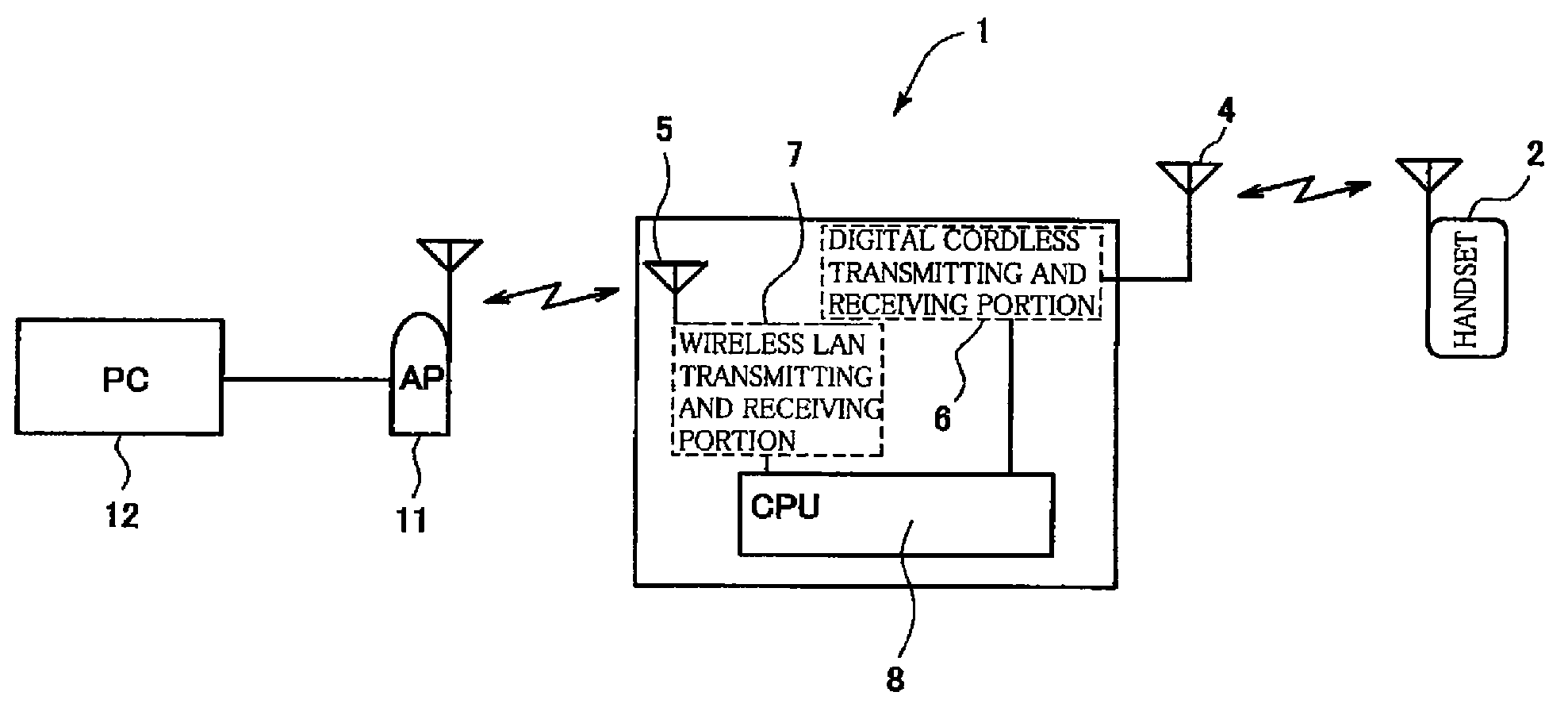
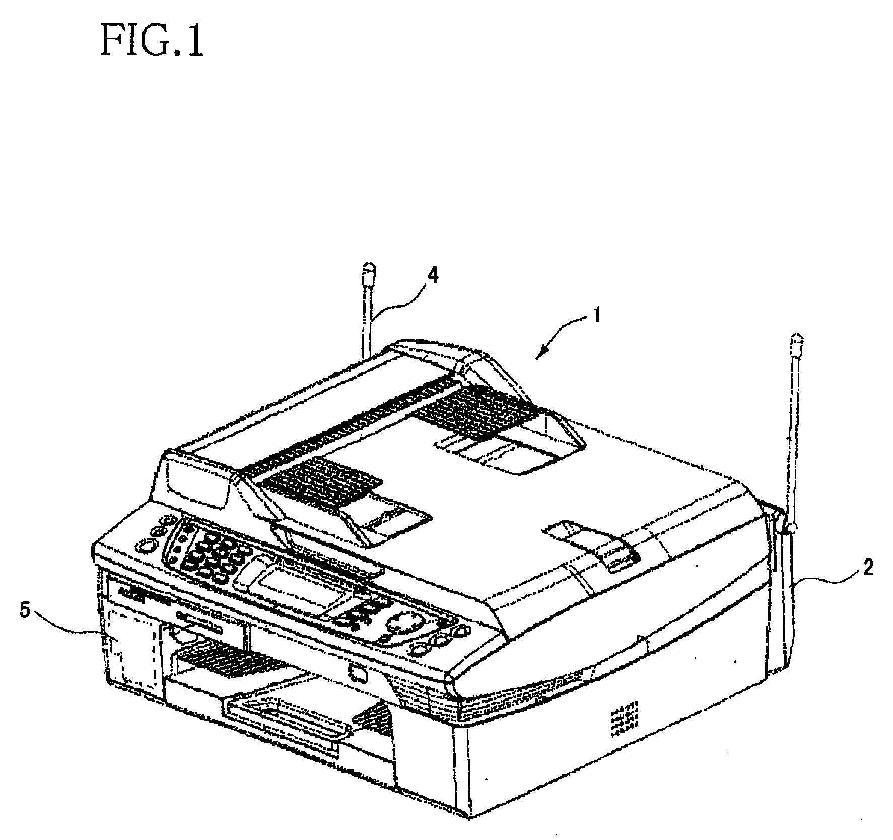
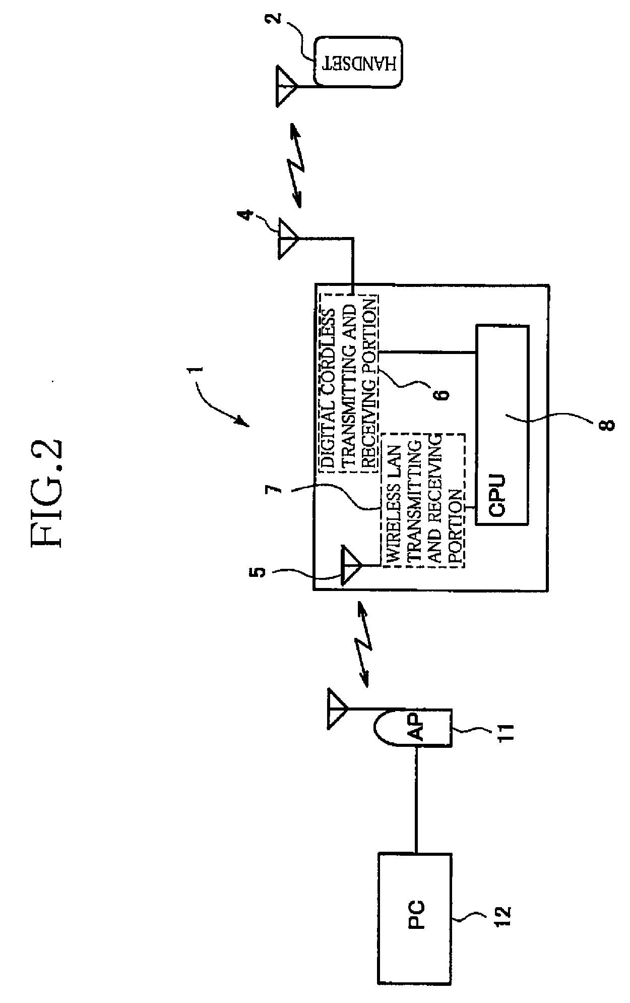
[0021]Hereinafter, there will be described a preferred embodiment of the present invention by reference to the drawings. It is to be understood that the following embodiment is described only by way of example, and the invention may be otherwise embodied with various modifications without departing from the scope and spirit of the invention. FIG. 1 is a perspective view of a wireless communication apparatus 1 as the embodiment of the present invention. The wireless communication apparatus 1 can establish two communication systems with various devices, i.e., a cordless phone system and a wireless LAN system. The wireless communication apparatus 1 is equipped with a handset 2 as a specific external communication device that is a digital cordless phone capable of communicating with the wireless communication apparatus 1 as a main unit configured to perform a cordless phone communication, a digital cordless antenna portion 4 for transmitting and receiving data when the wireless communic...


PUM


Abstract

A wireless communication apparatus including: a specific external communication section configured to communicate with a specific external communication device through a wireless communication while successively changing a communication frequency band that is a frequency band in which a communication is performed; and a communication condition recognizing section configured to recognize a communication condition in each of a plurality of frequency ranges each having a predetermined range width, wherein the specific external communication section determines, on the basis of the recognized communication condition in each of the plurality of frequency ranges, a set number of a plurality of communication planned frequency bands in each of which the specific external communication section is planned to communicate with the specific external communication device, by allocating to a part of the plurality of frequency ranges, and wherein the specific external communication section communicates, in the determined communication planned frequency bands, with the specific external communication device while successively changing the communication frequency band.

Description

CROSS REFERENCE TO RELATED APPLICATION[0001]The present application claims priority from Japanese Patent Application No. 2007-091610, which was filed on Mar. 30, 2007, the disclosure of which is herein incorporated by reference in its entirety.BACKGROUND OF THE INVENTION[0002]1. Field of the Invention[0003]The present invention relates to a wireless communication apparatus configured to communicate with a specific external communication device while successively changing a communication frequency band or a channel.[0004]2. Description of the Related Art[0005]As a technology for connecting a wireless LAN device, there is conventionally known an IEEE 802.11 standard, a Bluetooth (registered trademark) standard, and so on.[0006]The wireless LAN device and a digital cordless phone use the same 2.4 GHz frequency band. Thus, where the wireless LAN device and the digital cordless phone are used in the same area at the same time, a radio interference unfortunately occurs therebetween, resul...

Claims


Application Information

Patent Timeline
Patent Type & Authority Applications(United States)
IPC IPC(8): H04B7/208H04W24/00H04W72/00H04W88/02
CPCH04B1/713H04W72/1242H04W88/06H04W72/569
Inventor WAKIZAKA, MASAAKI
Owner BROTHER KOGYO KK
Learn More