
Moving picture coding apparatus and method

a coding apparatus and picture technology, applied in the field of moving picture coding apparatus and method, can solve problems such as the perception degradation of reconstructed pictures, and achieve the effects of reducing coding cost, distortion robustness, and distortion robustness

Inactive Publication Date: 2008-10-02
KK TOSHIBA
View PDF2 Cites 38 Cited by
  • Summary
  • Abstract
  • Description
  • Claims
  • Application Information

AI Technical Summary

Benefits of technology

[0014]According to the present invention, there is provided a moving picture coding apparatus which is adapted to suppress the perceptual degradation of reconstructed pictures even if the quantization step size is large.

Problems solved by technology

According to expressions 2 and 3 proposed in related art 1, the Lagrange multipliers λmode and λmotion depend only upon the quantization step size Q. Therefore, when the quantization step size Q is large, the Lagrange multipliers λmode and λmotion increase excessively, which might cause the code length, R, to be regarded as important more than necessary in computing the coding cost C. Regarding the code length, R, as important more than necessary in computing the coding cost C involves a problem particularly in pictures for which coding errors (distortion) between reconstructed pictures and original pictures are perceptible, which might cause perceptual degradation of reconstructed pictures.

Method used


Image

  • Moving picture coding apparatus and method
  • Moving picture coding apparatus and method
  • Moving picture coding apparatus and method

Examples


Embodiment Construction

[0025]An embodiment of the present invention will be described hereinafter with reference to the accompanying drawings.

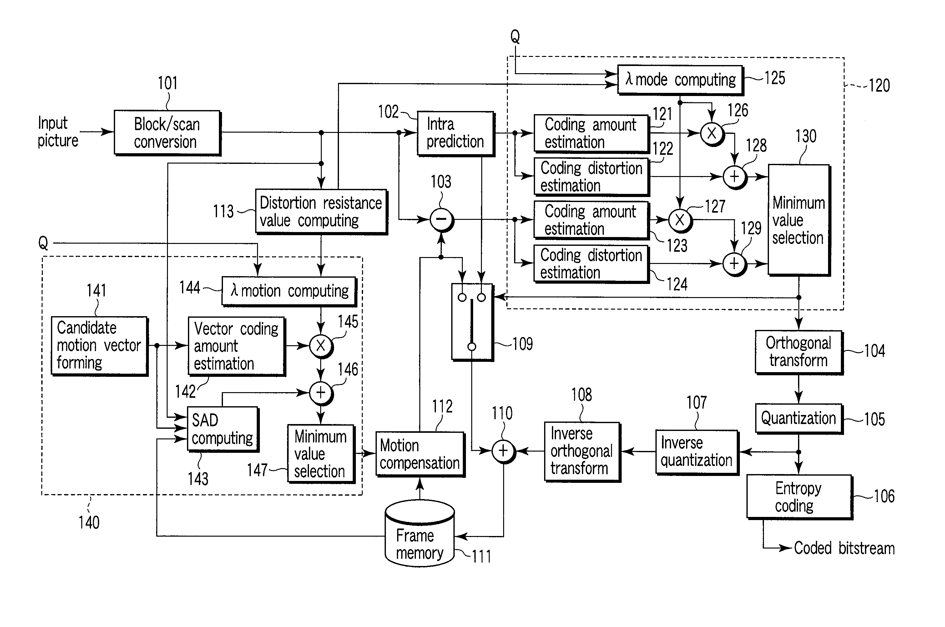
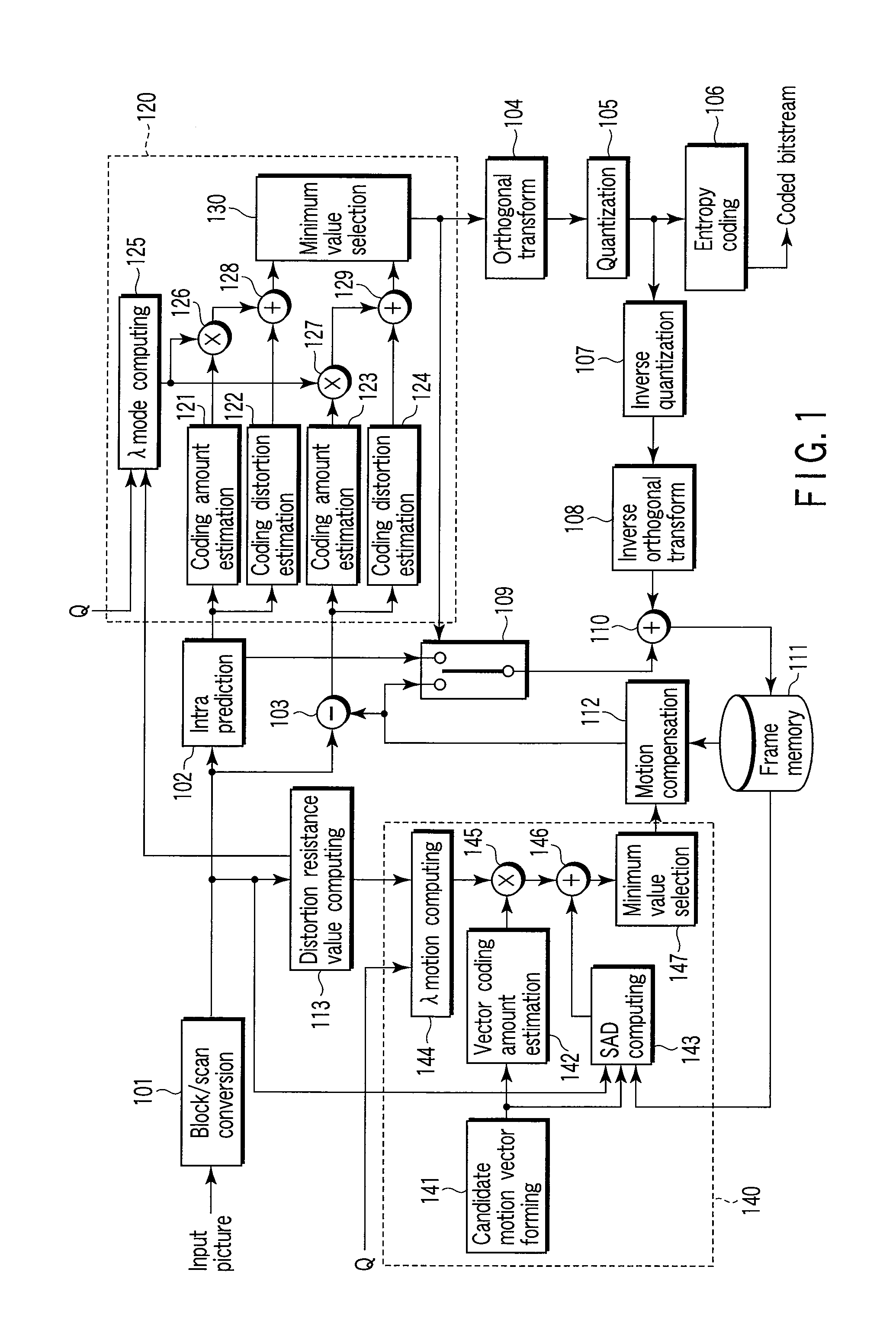
[0026]As shown in FIG. 1, a moving picture coding apparatus according to an embodiment of the present invention includes a block / scan converter 101, an intra prediction unit 102, a subtracter 103, an orthogonal transform unit 104, a quantization unit 105, an entropy coding unit 106, an inverse quantization unit 107, an inverse orthogonal transform unit 108, a selector 109, an adder 110, a frame memory 111, a motion compensation unit 112, a distortion robustness computing unit 113, a mode selection unit 120, and a motion vector estimation unit 140.

[0027]The mode selection unit 120 includes a coding amount estimation unit 121, a coding distortion estimation unit 122, a coding amount estimation unit 123, a coding distortion estimation unit 124, a λmode computing unit 125, a multiplier 126, a multiplier 127, an adder 128, an adder 129, and a minimum value selector 130. ...


PUM


Abstract

A moving picture coding apparatus includes a computing unit configured to compute a distortion robustness indicating degree of imperceptibility of coding distortion in a region to be coded in an input picture, an estimation unit configured to estimate coding distortions based on a first prediction residual of an intra predicted picture, and a second prediction residual of an inter predicted picture, an estimation unit configured to estimate code lengths to be generated when coding the first and second prediction residuals, a computing unit configured to compute coding costs of the first and second prediction residuals by weighted addition of the coding distortions and code lengths so that effect of the code lengths more increases than that of the coding distortions as the distortion robustness increases, a selection unit configured to select one of the first and second prediction residuals for which the coding cost is minimized.

Description

CROSS-REFERENCE TO RELATED APPLICATIONS[0001]This application is based upon and claims the benefit of priority from prior Japanese Patent Application No. 2007-087193, filed Mar. 29, 2007, the entire contents of which are incorporated herein by reference.BACKGROUND OF THE INVENTION[0002]1. Field of the Invention[0003]The present invention relates to a moving picture coding apparatus and method which selects the optimum prediction mode and motion vector using rate-distortion optimization.[0004]2. Description of the Related Art[0005]With MPEG-4 AVC / H.264, which is recently becoming the primary international standard for coding of moving pictures, a plurality of prediction modes has been set up in motion-compensated inter-frame prediction and intra-frame prediction. The optimum one is selected from these prediction modes for each block of an input picture to provide coding. With the inter prediction, the optimum motion vector is selected from among a plurality of candidate motion vector...

Claims


Application Information

Patent Timeline
IPC IPC(8): H04N7/32H04N19/50H03M7/40H04N19/107H04N19/109H04N19/11H04N19/126H04N19/136H04N19/137H04N19/14H04N19/147H04N19/149H04N19/154H04N19/167H04N19/176H04N19/186H04N19/19H04N19/196H04N19/503H04N19/51H04N19/593H04N19/60H04N19/61H04N19/85H04N19/91
CPCH04N19/56H04N19/176H04N19/147H04N19/567H04N19/107H04N19/17H04N19/61
Inventor KODAMA, TOMOYA
Owner KK TOSHIBA
Learn More