Precoding apparatus and method in a wireless communication system using multiple input multiple output
a wireless communication system and antenna technology, applied in multi-frequency code systems, diversity/multi-antenna systems, transmission monitoring, etc., can solve the problems of increasing the complexity of the receiver, increasing the load of cqi feedback, and restoring signals may include mutual interference, so as to achieve the effect of increasing transmission efficiency
- Summary
- Abstract
- Description
- Claims
- Application Information
AI Technical Summary
Benefits of technology
Problems solved by technology
Method used
Image
Examples
first embodiment
[0051]FIG. 4 is a block diagram illustrating an internal structure of a precoder according to the present invention.
[0052]Shown in FIG. 4 is a method for constructing a precoder with Kronecker product of the intra-group precoders and the inter-group precoders. When four transmit antennas are used, a maximum of four modulation symbol streams can be transmitted, wherein the modulation symbol streams 1 and 2 form an antenna group and the modulation symbol streams 3 and 4 from another antenna group. Modulation symbol streams 1 and 3 make a pair, modulation symbol streams 2 and 4 make a pair, and the paired streams are input to first and second inter-group precoders 301a and 301b, respectively. The first and second inter-group precoders 301a and 301b perform the same function. A first output of the first inter-group precoder 301a becomes a first input of a first intra-group precoder 303a, and a second output of the first inter-group precoder 301a becomes a first input of a second intra-g...
second embodiment
[0055]FIG. 5 is a block diagram illustrating an internal structure of a precoder according to the present invention.
[0056]While the foregoing structure of FIG. 4 equally sets the intra-group precoders 303a and 303b, a structure of FIG. 5 differently sets the intra-group precoders for each group. If an intra-group precoder A 303 applied to an antenna group A to which precoding symbol streams 1 and 2 will be applied, uses a precoding matrix E1(A), and an intra-group precoder B 305 applied to an antenna group B to which precoding symbol streams 3 and 4 will be applied, uses a precoding matrix E1(B), the operation of FIG. 5 can be expressed as shown in Equation (12).
E=[E1(A)00E1(B)]P[E200E1]P(12)
[0057]The structure of FIG. 5 is designed taking into account the case where it is advantageous to use different beamformings as antenna groups show different spatial characteristics. The intra-group precoders 303 and 305 have the characteristics that they can form different beams.
third embodiment
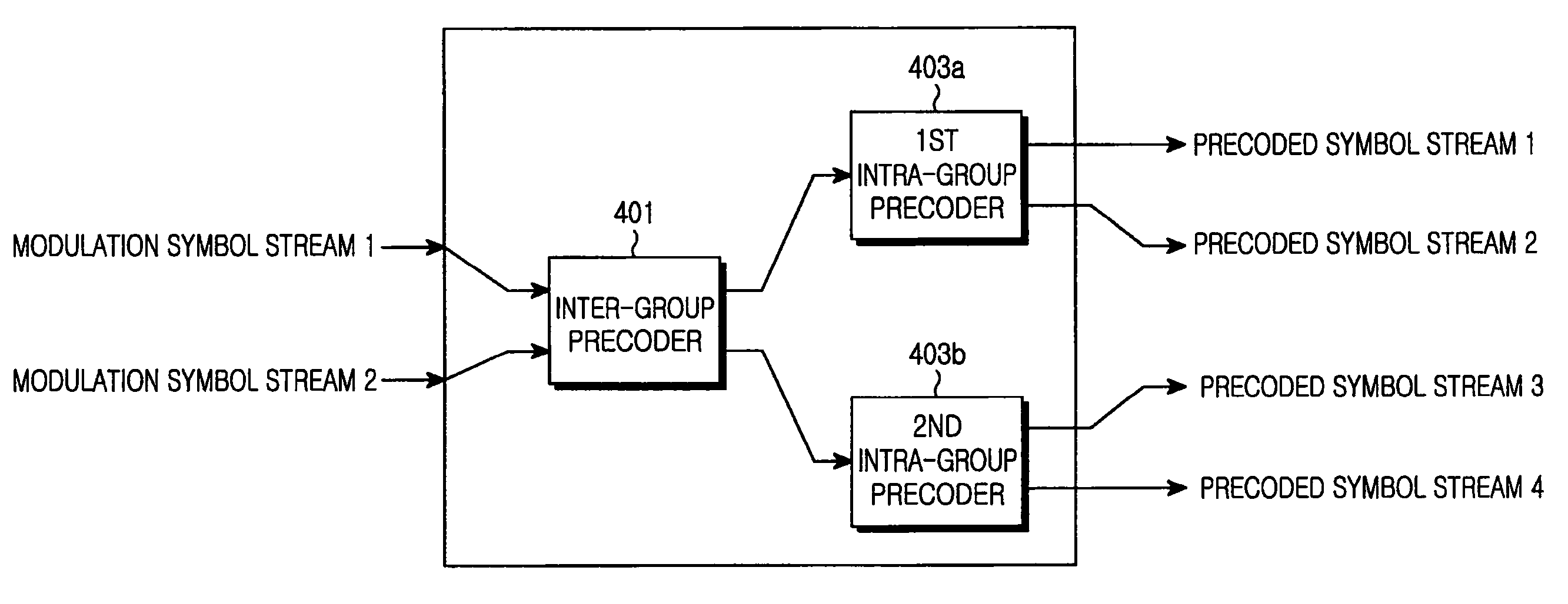
[0058]FIG. 6 is a block diagram illustrating an internal structure of a precoder according to the present invention.
[0059]FIG. 6 illustrates a structure of a precoder suitable for the case where it is possible to transmit only one signal stream with multiple antennas in the transmit antenna group since the spatial correlation in the transmit antenna group is very high. The MIMO transmitter generally needs Rank adaptation which is a function of adjusting the number of transmission signal streams according to the characteristic of the MIMO channel. If the foregoing structure of FIG. 4 has determined to transmit less than two signal streams through Rank adaptation, it is preferable that its operation is modified to the operation shown in FIG. 6. A modulation symbol stream 1 and a modulation symbol stream 2 are converted into two precoded signal streams by means of an inter-group precoder 401, and are input to intra-group precoders 403a and 403b, respectively. The intra-group precoders ...
PUM
 Abstract
Description
Claims
Application Information
 - R&D
- Intellectual Property
- Life Sciences
- Materials
- Tech Scout
- Unparalleled Data Quality
- Higher Quality Content
- 60% Fewer Hallucinations
Browse by: Latest US Patents, China's latest patents, Technical Efficacy Thesaurus, Application Domain, Technology Topic, Popular Technical Reports.
© 2025 PatSnap. All rights reserved.Legal|Privacy policy|Modern Slavery Act Transparency Statement|Sitemap|About US| Contact US: help@patsnap.com


