Free-Space Communications System and Method

a free-space communication and communication system technology, applied in the field of free-space communications systems and methods, can solve the problems of reducing the ‘quality’ being extremely technically sophisticated, and being incredibly expensive to design, build and use., and achieve the effect of improving the quality of the received communications signal

Inactive Publication Date: 2008-10-02
LOCKHEED MARTIN CORP
View PDF5 Cites 18 Cited by
  • Summary
  • Abstract
  • Description
  • Claims
  • Application Information

AI Technical Summary

Problems solved by technology

Unlike a fiber-based communications system, in which an optical fiber waveguide provides a relatively unobstructed and protected path for the transmission signal to the receiver platform, an exemplary signal-carrying infrared laser beam propagating over a free-space signal transmission path close to the earth's surface will encounter atmospheric conditions that reduce the ‘quality’ of the received communications signal.
These techniques and variations of each that are known in the art, and which are successful to varying degrees in increasing free-space communications distances and received signal quality, suffer from the reality that they are extremely technically sophisticated and incredibly expensive to design, build and use.

Method used


Image

  • Free-Space Communications System and Method
  • Free-Space Communications System and Method
  • Free-Space Communications System and Method

Examples


Embodiment Construction

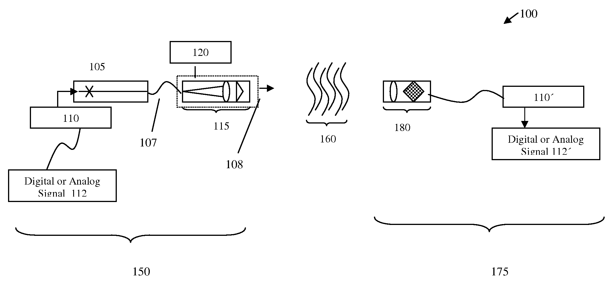
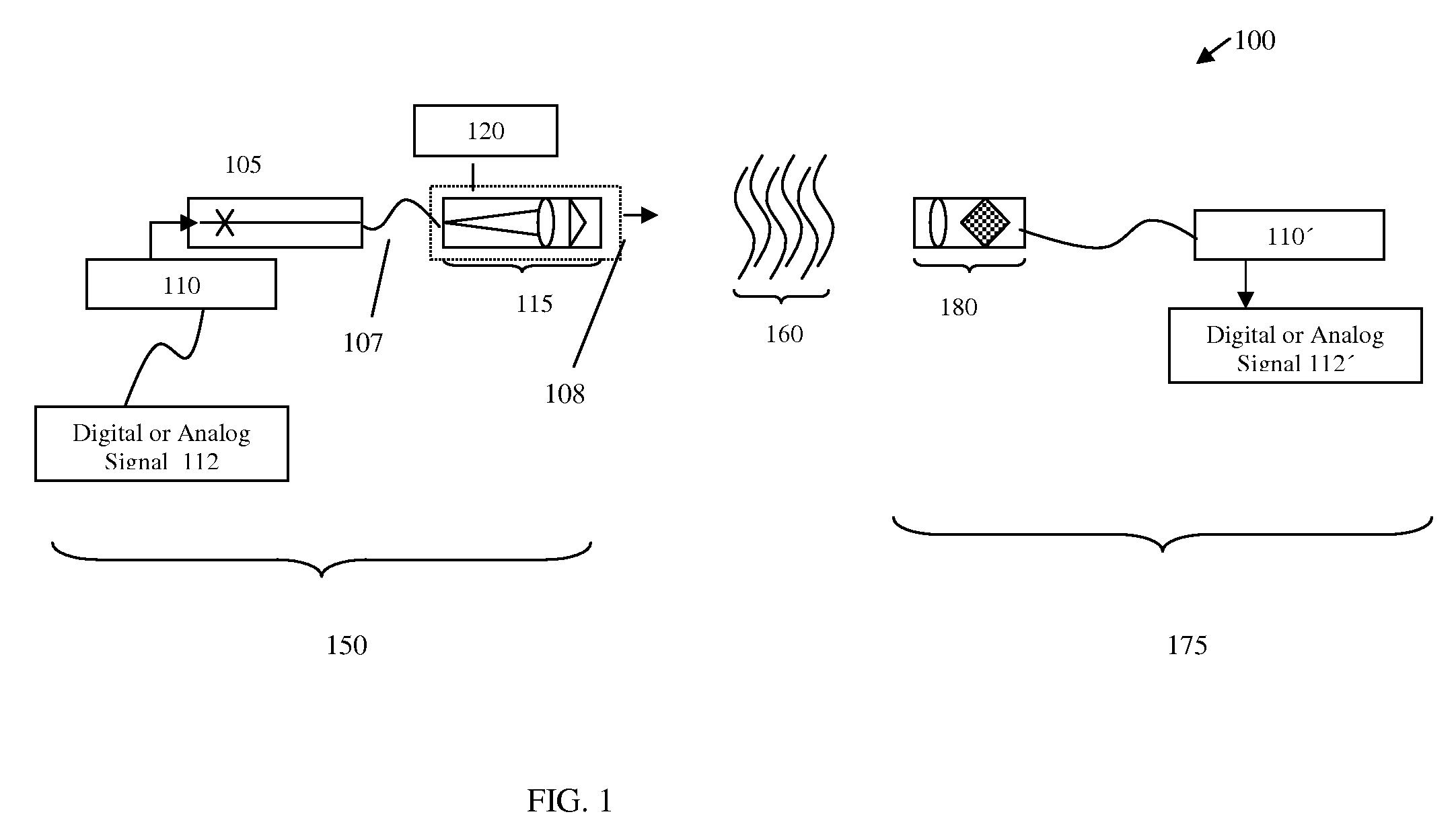
[0020]An illustrative embodiment of the invention is directed to a free-space communications system 100 (“the system”) as shown in the block diagram of FIG. 1. The system 100 as shown includes a signal transmitter platform 150 and a signal transmission receiver platform 175 separated by a turbulent free-space transmission medium 160.

[0021]The signal transmitter platform 150 is comprised of a source beam generator 105 such as a coherent or semi-coherent laser source (e.g., diode laser, fiber laser, SLD, etc.) that generates a diffracting type beam 107 having a Gaussian transverse intensity distribution. Auxiliary optics (not shown) may be used to condition the output from the source beam generator 105. In an exemplary aspect, the signal laser wavelength is 1.3 micrometers. A modulator 110, driven by a digital or analog signal driver 112, is operatively connected to the laser source. The modulator modifies the phase, amplitude, or both the phase and amplitude of the source signal 107....


PUM


Abstract

Embodiments of the invention are directed to a free-space communications system, a signal transmission platform for a free-space communications system, and a method for free-space communications, that advantageously provide or have the potential to provide measurable improvements in free-space communications over a turbulent atmospheric transmission path. A principal feature of all of the embodiments disclosed herein is the generation of a pseudo-non-diffracting communications signal transmission beam, referred to herein as a ‘non-diffracting signal transmission beam’. A realizable embodiment of such a non-diffracting signal transmission beam known in the art is a Bessel beam. A free-space communications system includes a communications signal transmitter platform that ultimately can generate a particularly specified transmission signal waveform, which is a non-diffracting signal transmission beam. The free-space communications system also includes a communications signal receiver platform that is located along a free-space communications signal transmission path. By modifying the signal light source from Gaussian to Bessel or other non-diffracting type beams, intensity stability under turbulence is improved. This passive technique, by virtue of increased intensity stability, may help to maintain bit error rate performance under turbulence.

Description

FIELD OF THE INVENTION[0001]Embodiments of the invention are directed to a free-space communications system and method, and more particularly, to a free-space communications system, signal transmission platform and free-space communications method that offer improved communications performance over a turbulent free-space transmission medium.DESCRIPTION OF RELATED ART[0002]Free-space optical communications, alternatively referred to as optical wireless transmission or fiber-less optical transmission, and by analogous monikers, is simple in concept: a communications signal in the form of a narrow laser beam is sent from a transmitter to a receiver over a straight line optical path through the atmosphere. Beam steering components may be utilized to bend or direct the optical transmission path, but for the purpose of the invention embodiments described herein, the communications system can be viewed as a line-of-sight system. Unlike a fiber-based communications system, in which an optic...

Claims


Application Information

Patent Timeline
Patent Type & Authority Applications(United States)
IPC IPC(8): H04J14/02
CPCH04B10/1121
Inventor WERNER, WALTER V.HAYS, PARK E.
Owner LOCKHEED MARTIN CORP
Why Eureka
Try Eureka