
Connection of components of a wind turbine

a technology for wind turbines and components, applied in the direction of wind energy generation, liquid fuel engine components, non-positive displacement fluid engines, etc., to achieve the effect of higher friction coefficients and higher friction coefficients of connection

Active Publication Date: 2008-10-02
SIEMENS GAMESA RENEWABLE ENERGY SERVICE GMBH
View PDF14 Cites 17 Cited by
  • Summary
  • Abstract
  • Description
  • Claims
  • Application Information

AI Technical Summary

Benefits of technology

[0011]Moreover, the connection is characterized in that the surface of the contact surface of the second component has a higher roughness than the surface of the contact surface of the first component. The micro-plastic deformation in the soft surface of the contact surfaces of the first component is hereby improved. Overall, this increases the frictional connection of the components of a wind turbine that are to be connected.

Problems solved by technology

This is especially important in the use or installation of wind turbines because the wind turbine is either installed or repaired under very unfavorable installation and repair conditions.

Method used


Image

  • Connection of components of a wind turbine
  • Connection of components of a wind turbine
  • Connection of components of a wind turbine

Examples


Embodiment Construction

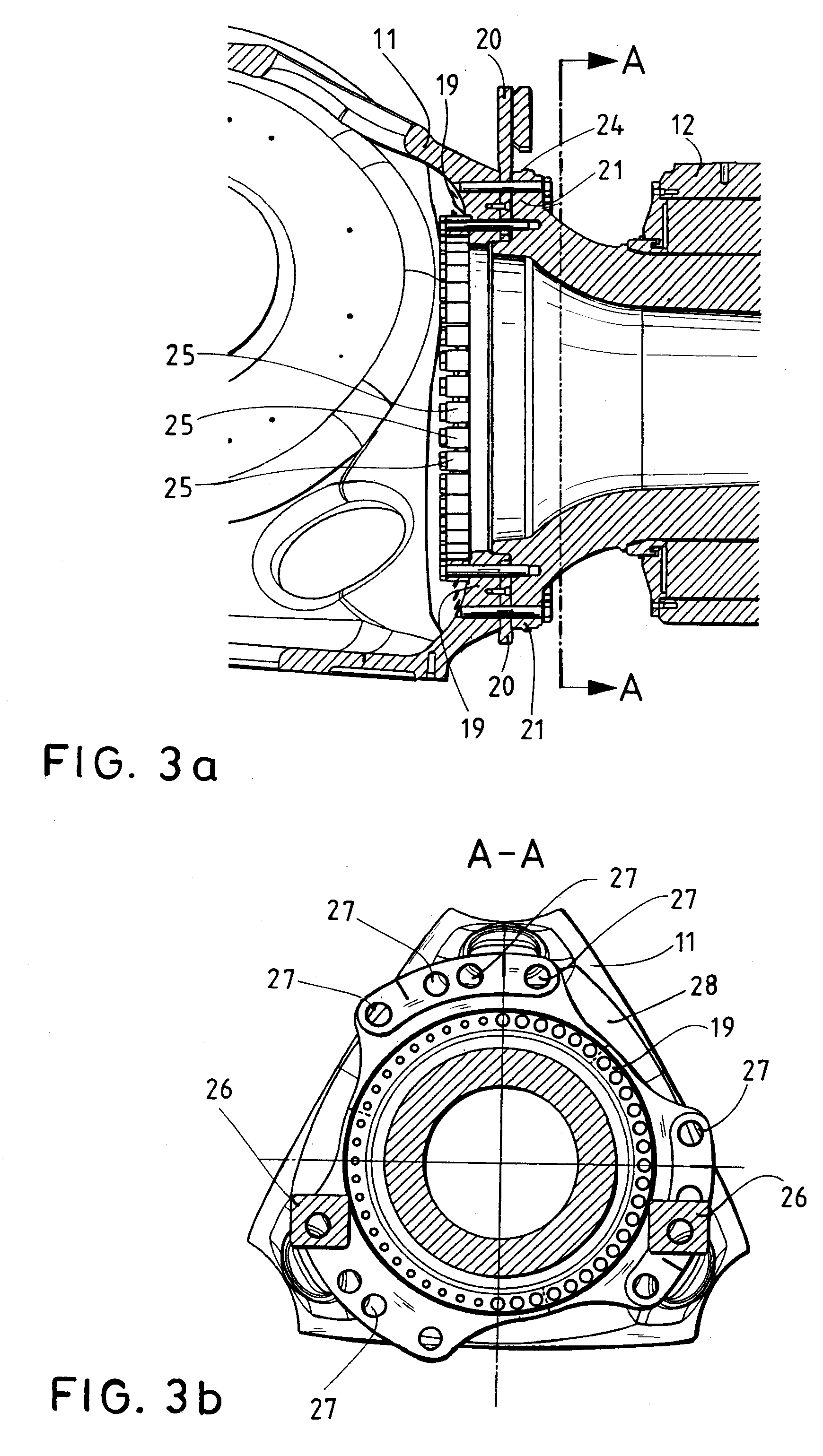
[0040]In the following figures, for simplicity the same or similar types of elements or corresponding parts are provided with the same reference numbers.

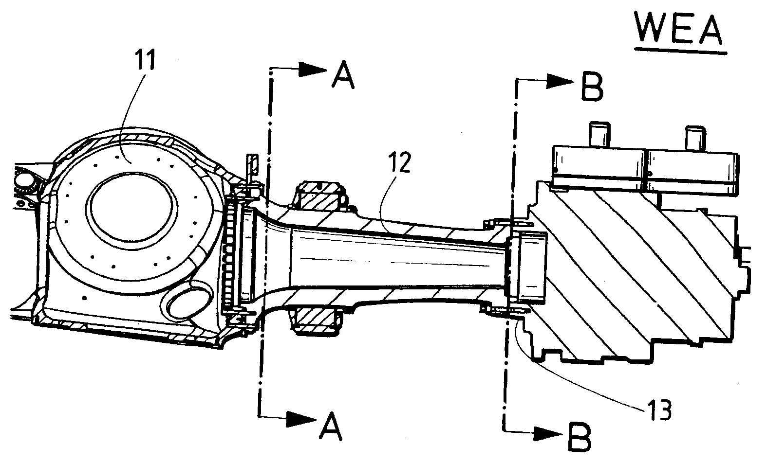
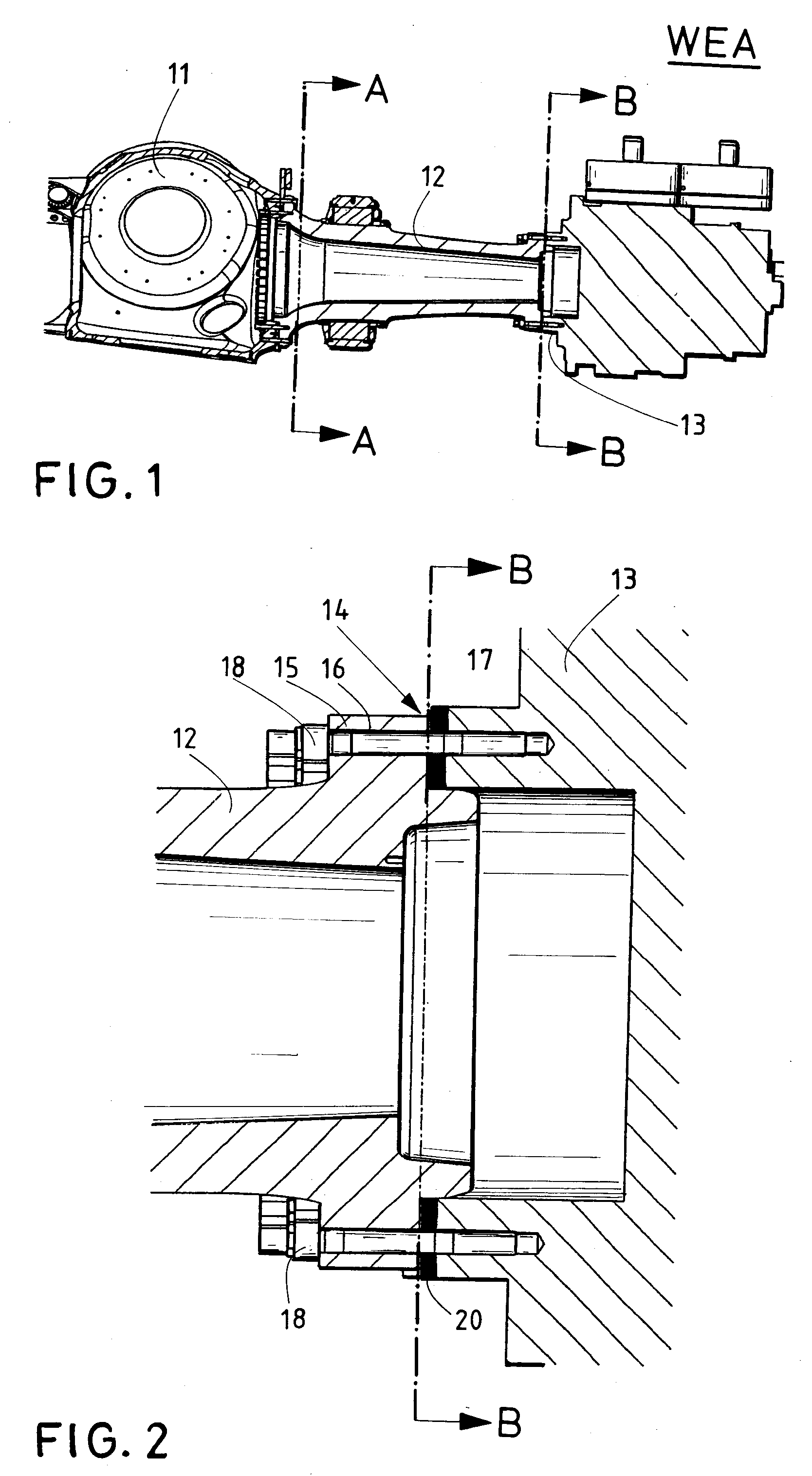
[0041]FIG. 1 shows a cross-section of a connected arrangement of a rotor hub 11 with a rotor shaft 12 and a connection part 13 of a corresponding gear of a wind turbine. The rotor hub 11, the rotor shaft 12 and the gear (not shown), which has the connection part 13 in the front area, are parts of a schematically indicated wind turbine WEA.

[0042]As shown in FIG. 2, the rotor shaft 12 is connected with the connection part 13 of the gear by means of a flange connection 14. For this, the rotor shaft 12 has a flange ring 15 on the end facing the connection part 13, which has corresponding bore holes 16 for receiving screws. The bore holes 16 are arranged at regular intervals around the perimeter of the flange ring 15. The connection part 13 of the gear has corresponding tapped blind holes 17 on the side facing the rotor shaft 12, which h...


PUM


Abstract

The invention relates to a connection between components of a wind turbine. More specifically, the present invention relates to components for a wind turbine having a diameter of more than 0.5 m, preferably more than 1.0 m, and more preferably more than 1.5 m. The wind turbine includes two components that are connected together, whereby each component has a contact surface. The surface of the contact surface of a first component is softer than the surface of the contact surface of a second component. Further, the surface of the contact surface of the second component is annealed.

Description

BACKGROUND OF THE INVENTION[0001]The present invention relates to components for a wind turbine. More specifically, the present invention relates to a connection between components for a wind turbine having a diameter of more than 0.5 m, wherein the components each have a contact surface.[0002]In order to connect large-volume components of a wind turbine during installation, maintenance, or repair, flange connections or screw connections are provided between components, such as between a rotor shaft and a drive input or between the rotor shaft and a rotor hub.[0003]In addition, screw connections are provided between the connection of a tubular tower and a pivot bearing or between a machine support and other components such as a rotor mount, a gearbox mounting, an axle journal, or a (ring) generator.[0004]Based on this state of the art, the object of the invention is to improve the connection between large-volume components of a wind turbine, where it should be possible to increase t...

Claims


Application Information

Patent Timeline
Patent Type & Authority Applications(United States)
IPC IPC(8): F03D11/00
CPCF03D11/00F03D11/04F05B2230/25F05B2230/41Y10T403/64F05B2280/5007F05C2251/10Y02E10/721Y02E10/728F05B2230/90F16D1/033F03D13/20F03D15/10F03D80/00F16B2200/50Y02E10/72Y02P70/50
Inventor EUSTERBARKEY, CARSTEN
Owner SIEMENS GAMESA RENEWABLE ENERGY SERVICE GMBH
Learn More