Balanced variable displacement vane pump with floating face seals and biased vane seals

Active Publication Date: 2008-10-02
TRIUMPH ENGINE CONTROL SYST
View PDF12 Cites 24 Cited by
  • Summary
  • Abstract
  • Description
  • Claims
  • Application Information

AI Technical Summary

Benefits of technology

[0014]Preferably, a pump assembly in accordance with the subject disclosure includes axially floating annular face seals positioned between the rotor faces and the inner surfaces of the front and rear side plates. These dynamic face seals are pushed against the respective side plates by the discharge pressure of the pump to reduce radial leakage within the pump cartridge.
[0016]In accordance with a preferred embodiment of the subject invention, each vane has dual radially outer vane tips and dual front and rear vane tips for maintaining the hydrostatic balance of the vane. In addition, two radial bores extend through each vane to allow fluid discharge pressure to act on the overvane surface, further maintaining the hydrostatic balance of the vane. Preferably, each vane has front and rear spring loaded dynamic face seals that act against the front and rear face plates to reduce circumferential leakage between adjacent vane buckets or volume chambers.
[0018]The pump assembly may also include floating front and rear rotor seals for reducing radially inward leakage. Each rotor seal is disposed within a groove formed in the rotor, wherein the high pressure fluid urges the front and rear rotor seals axially outward from the pumping chamber to create an effective seal between the rotor seals and the respective side plate.
[0020]It is envisioned that the variable displacement vane pump assembly may also have vane assemblies with front and rear spring loaded dynamic face seals acting against the front and rear face plates, to reduce circumferential leakage between adjacent vane buckets.

Problems solved by technology

Further, these rotor reaction forces may disrupt or cause poor operation of the pump and / or poor operation of the system containing the pump.

Method used


Image

  • Balanced variable displacement vane pump with floating face seals and biased vane seals
  • Balanced variable displacement vane pump with floating face seals and biased vane seals
  • Balanced variable displacement vane pump with floating face seals and biased vane seals

Examples


Embodiment Construction

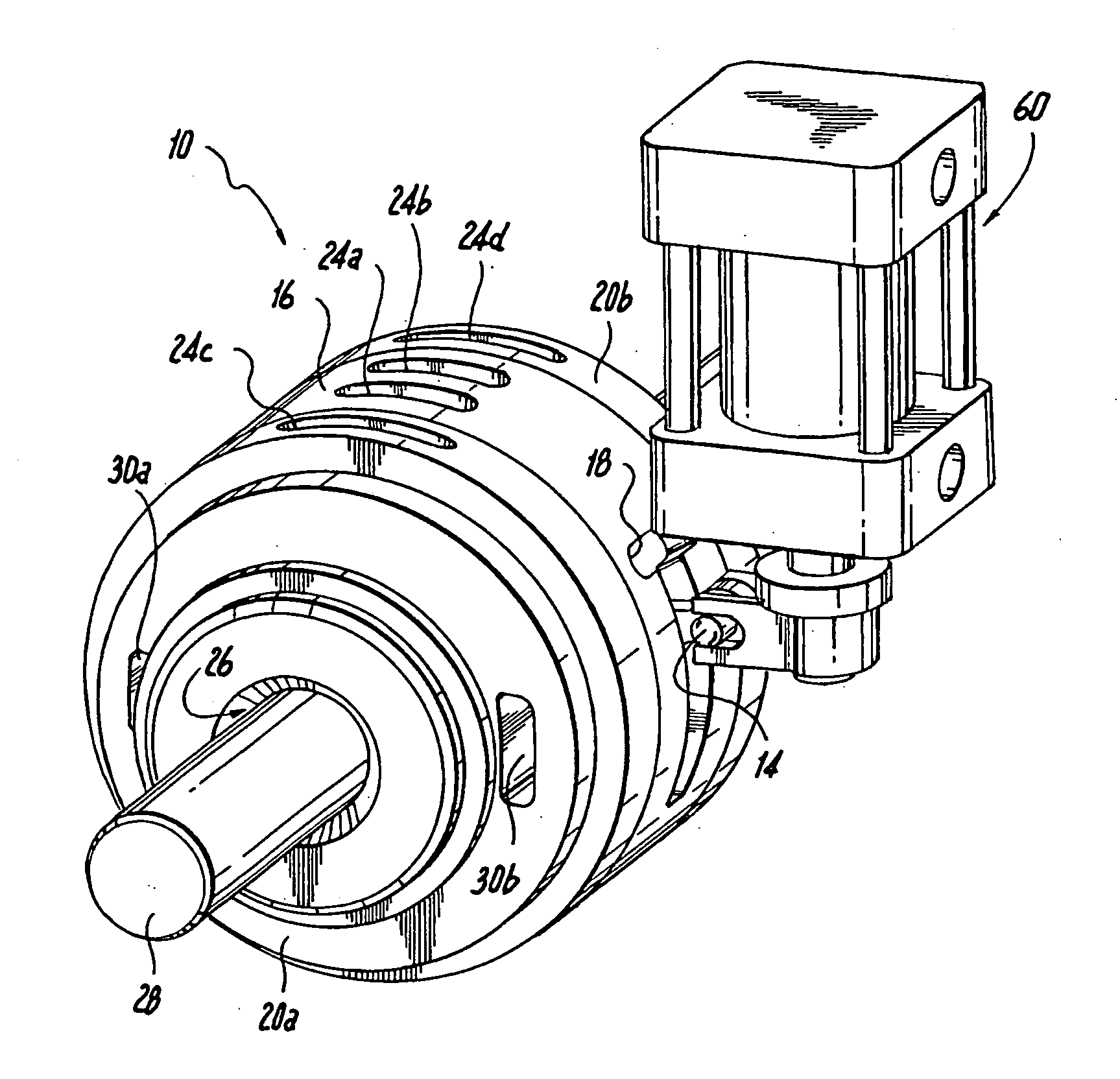
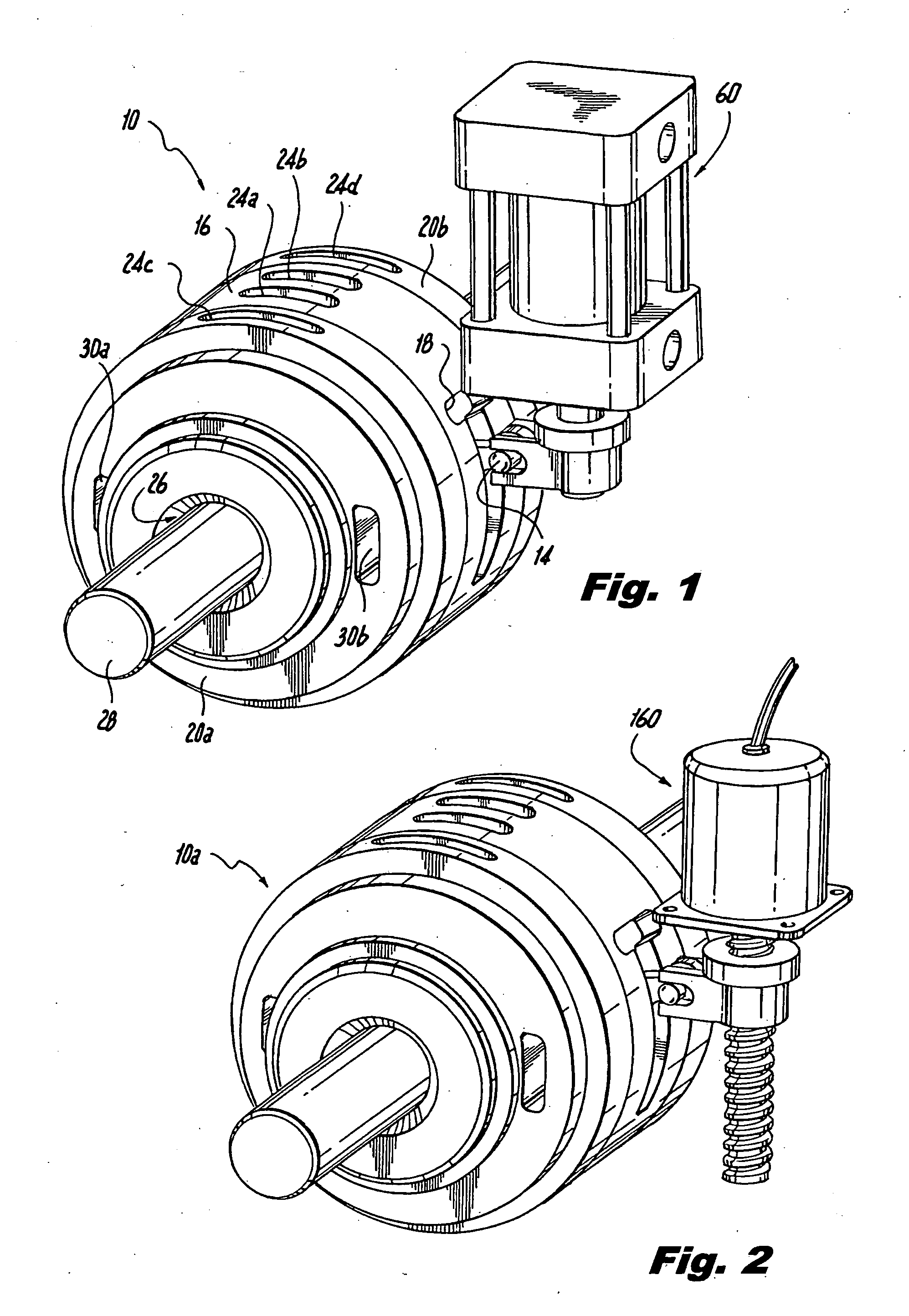
[0037]Referring now to the drawings wherein like reference numerals identify similar structural feature or elements of the subject invention, there are illustrated in FIGS. 1 and 2 two versions of a fully hydrostatically balanced variable displacement vane pump constructed as a cartridge assembly and designated generally by reference numerals 10 and 10a, respectively. The cartridge or pump assemblies 10, 10a are configured to fit within a reusable housing (not shown). In other words, the pump assemblies 10, 10a can be readily replaced when worn or in need of repair. All relative descriptions herein such as front, rear, side, left, right, up, and down are with reference to the Figures, and not meant in a limiting sense.

[0038]Vane pump assemblies 10, 10a are substantially identical except for the respective drive mechanism 60, 160 used to control the displacement of the pump assemblies 10, 10a. As shown in FIG. 1, the drive mechanism 60 may be a linear actuator such as a hydraulic cyl...


PUM


Abstract

A vane pump assembly including a cam ring having an elliptical inner bore defining a hydraulic pumping chamber, the pumping chamber having an interior camming surface. The cam ring defines ports for admitting fluid into the pumping chamber. A rotor, within the cam ring, defines a plurality of radial vane slots. A vane assembly is supported in each vane slot to define vane buckets. Each vane assembly has an end dynamic vane seal for reducing leakage between the buckets. Front and rear side plates, separated by an annular spacer, enclose the pumping chamber. The pump assembly may also include floating front and rear rotor seals for reducing radially inward leakage. Each rotor seal is disposed within a groove formed in the rotor, wherein discharge pressure urges the rotor seals axially outward from the pumping chamber to create an effective seal against the respective side plate.

Description

CROSS-REFERENCE TO RELATED APPLICATION[0001]This application claims priority to U.S. Provisional Patent Application No. 60 / 920,477, filed Mar. 28, 2007, which is incorporated herein by reference in its entirety.BACKGROUND OF THE INVENTION[0002]1. Field of the Invention[0003]The subject invention is directed to a variable displacement vane pump, and more particularly, to a hydrostatically balanced multi-action variable displacement vane pump with variable cam timing, vane seals for reducing internal cross-bucket leakage, and floating face seals for reducing radial leakage.[0004]2. Description of Related Art[0005]Variable displacement vane pumps are well known in the art, and have been employed as fuel pumps in aircraft from many years. Most variable displacement vane pumps utilize a single lobe cam ring design, as disclosed for example in U.S. Pat. No. 5,545,014, U.S. Pat. No. 5,545,018 and U.S. Pat. No. 6,719,543, the disclosures of which are herein incorporated by reference in thei...

Claims


Application Information

Patent Timeline
IPC IPC(8): F04B23/10
CPCF01C21/106F04C2/3446F04C14/14F04C15/0023F05C2225/00F04C15/0038F04C2/344F04C14/20F04C14/223
Inventor DONG, XINGEN
Owner TRIUMPH ENGINE CONTROL SYST
Why Eureka
Try Eureka