
A liquid-filled cage ball type aortic valve stent system

A technology of aortic valve and stent system, which is applied in the field of medical devices and interventional therapy devices, and can solve the circumferential leakage of valve stents and tri-leaflet biological valves, obstruction of coronary blood flow, and central regurgitation of tri-leaflet biological valves Service life and other issues, to avoid obstructing coronary blood flow, eliminate central regurgitation, and prolong service life

Active Publication Date: 2016-08-17
BEIJING UNIV OF TECH
View PDF11 Cites 0 Cited by
  • Summary
  • Abstract
  • Description
  • Claims
  • Application Information

AI Technical Summary

Problems solved by technology

[0004] In order to overcome the existing aortic valve stent system inserted into the heart, there is circumferential leakage between the valve stent and the three-leaflet biological valve, the center of the three-leaflet biological valve has problems of regurgitation and short service life, and to reduce the interventional band The stent system of the tri-leaf bioprosthetic valve has the risk of the leaflets obstructing the blood flow of the coronary arteries. The present invention provides a liquid-filled cage-type aortic valve stent system

Method used


Image

  • A liquid-filled cage ball type aortic valve stent system
  • A liquid-filled cage ball type aortic valve stent system
  • A liquid-filled cage ball type aortic valve stent system

Examples


Embodiment Construction

[0018] The present invention will be further described below in conjunction with the accompanying drawings and embodiments.

[0019] In order to make the object, technical solution and advantages of the present invention clearer, the present invention will be further described in detail below in conjunction with the accompanying drawings and embodiments. It should be understood that the specific embodiments described here are only used to explain the present invention, not to limit the present invention.

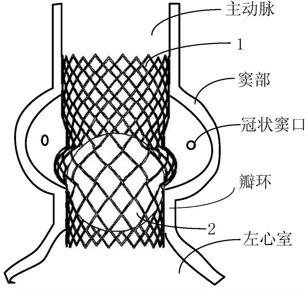
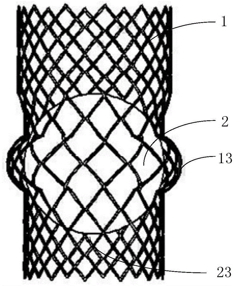
[0020] refer to figure 1 , the working position of the liquid-filled ball cage aortic valve stent system in the heart. In this embodiment, the system includes a stent main body 1 and a liquid-filled ball 2 . The main body 1 of the stent is anchored on the aorta and annulus after being transported to the position of the patient's aortic valve through the human artery or the apex of the heart. The fluid-filled ball 2 is installed in the main body 1 of the stent. Driven by mo...


PUM


Abstract

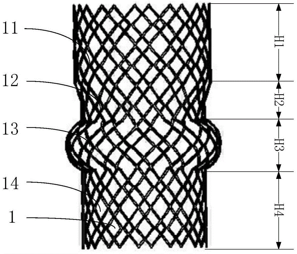
The invention provides a liquid injection type cage ball aortic valve support system and belongs to the technical field of medical instruments. The liquid injection type cage ball aortic valve support system comprises a support body and a liquid injection ball. The system is delivered to the position of the aortic valve of a patient through a catheter after passing through the artery or the cardiac apex of the human body, so that the lesion aortic valve is substituted, and the system controls the blood to flow from the left ventricle to the artery blood vessel in one direction. The support body is divided into four sections which are the valve ring anchoring section, the ball cage section, the transitional section and the aorta anchoring section in sequence. The liquid injection ball moves in the ball cage section of the support body in a reciprocating mode, so that the function of blood one-way flow control is achieved. The liquid injection type cage ball aortic valve support system has the advantages that the system can be implanted into the human body through the catheter and circumferential leakage can be reduced in the valve closing process; the liquid injection ball is adopted in a valve support so that the function of blood one-way flow control can be achieved and the center backflow phenomenon generated when valve leaflets are folded can be eliminated; the force receiving state of the liquid injection ball is better than that of a triple lobe type valve and the service life can be prolonged.

Description

technical field [0001] The invention belongs to the technical field of medical devices, more specifically to the field of interventional therapy devices, in particular to a liquid-filled ball cage type aortic valve stent system. Background technique [0002] In patients with aortic stenosis, if advanced age with severe comorbidities (European Heart Surgery Risk Assessment score greater than 20), secondary surgery with coronary artery bypass graft graft patency and other risk factors, and Patients with calcified aorta are at great risk for conventional aortic valve replacement surgery. The current treatment for the above patients is transfemoral, left axillary or apical catheter aortic valve stent implantation. [0003] The existing aortic valve stent implantation is to install a biological valve on a self-expanding or balloon-expanded stent, and deliver it to the position of the patient's aortic valve through a catheter through the human artery or through the apex of the he...

Claims


Application Information

Patent Timeline
Patent Type & Authority Patents(China)
IPC IPC(8): A61F2/24
CPCA61F2/2418A61F2/2424
Inventor 乔爱科潘友联
Owner BEIJING UNIV OF TECH
Learn More