Cylinder dynamic seal apparatus used for Calor fluid machine

A fluid machinery and dynamic sealing technology, applied in liquid variable volume machinery, mechanical equipment, machines/engines, etc., can solve problems such as circumferential leakage, and achieve the effect of reducing leakage and improving the efficiency of adiabatic indication.

Inactive Publication Date: 2008-10-08
XI AN JIAOTONG UNIV
View PDF0 Cites 1 Cited by
  • Summary
  • Abstract
  • Description
  • Claims
  • Application Information

AI Technical Summary

Problems solved by technology

[0007] The purpose of the present invention is to provide a cylinder body dynamic sealing device for Carroll fluid machinery, which solves the sealing problem of the existing Carroll fluid machinery cylinder working chamber end through the rotating cylinder body and the casing's matching gap.
It can effectively reduce the circumferential leakage of the conveyed medium in the working chamber of the cylinder through the gap at the end of the working chamber. While improving the volumetric efficiency and thermal efficiency of Carroll fluid machinery, it will not cause serious friction and thermal deformation of parts. And jamming, and the increase of friction that leads to the reduction of mechanical efficiency and other problems

Method used


Image

  • Cylinder dynamic seal apparatus used for Calor fluid machine
  • Cylinder dynamic seal apparatus used for Calor fluid machine
  • Cylinder dynamic seal apparatus used for Calor fluid machine

Examples


Embodiment Construction

[0028] Below in conjunction with accompanying drawing, specific embodiment of the present invention is described in further detail:

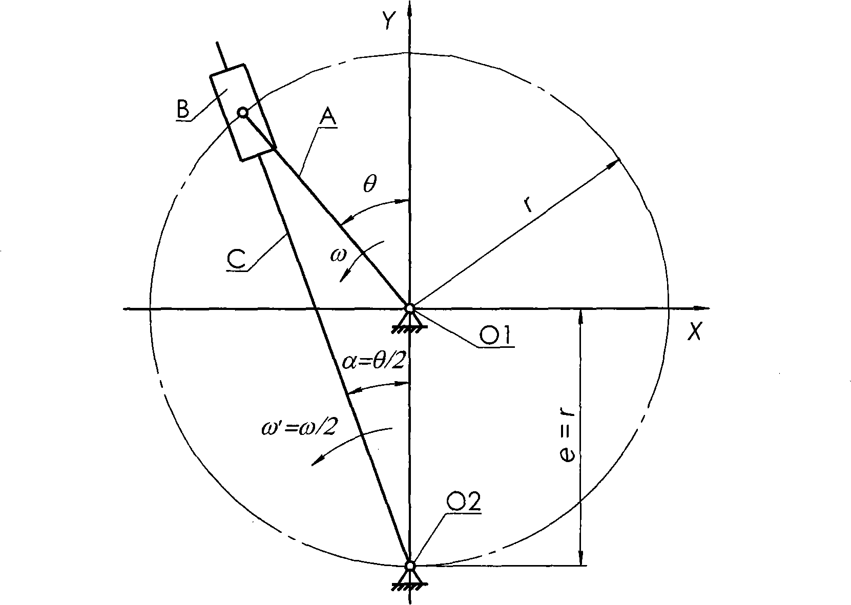
[0029] figure 1 It is a principle diagram of the mechanism motion transformation relation of the Carroll fluid machine targeted by the present invention. The slider in the figure is equivalent to the piston, the guide rod is equivalent to the cylinder hole, and the distance e between the cylinder body (ie the guide rod) and the center of the main shaft (ie the crank) is just equal to the crank radius r. When the crank drives the slider to rotate, the slider slides along the guide rod, and drives the guide rod to rotate at a half-synchronous rotation speed of the crank. Every time the crank rotates one revolution, the slider travels 4r along the guide rod. In the mechanism with only one slider and guide rod, when the crank angle is 180°, there is uncertainty in the direction of rotation of the guide rod.

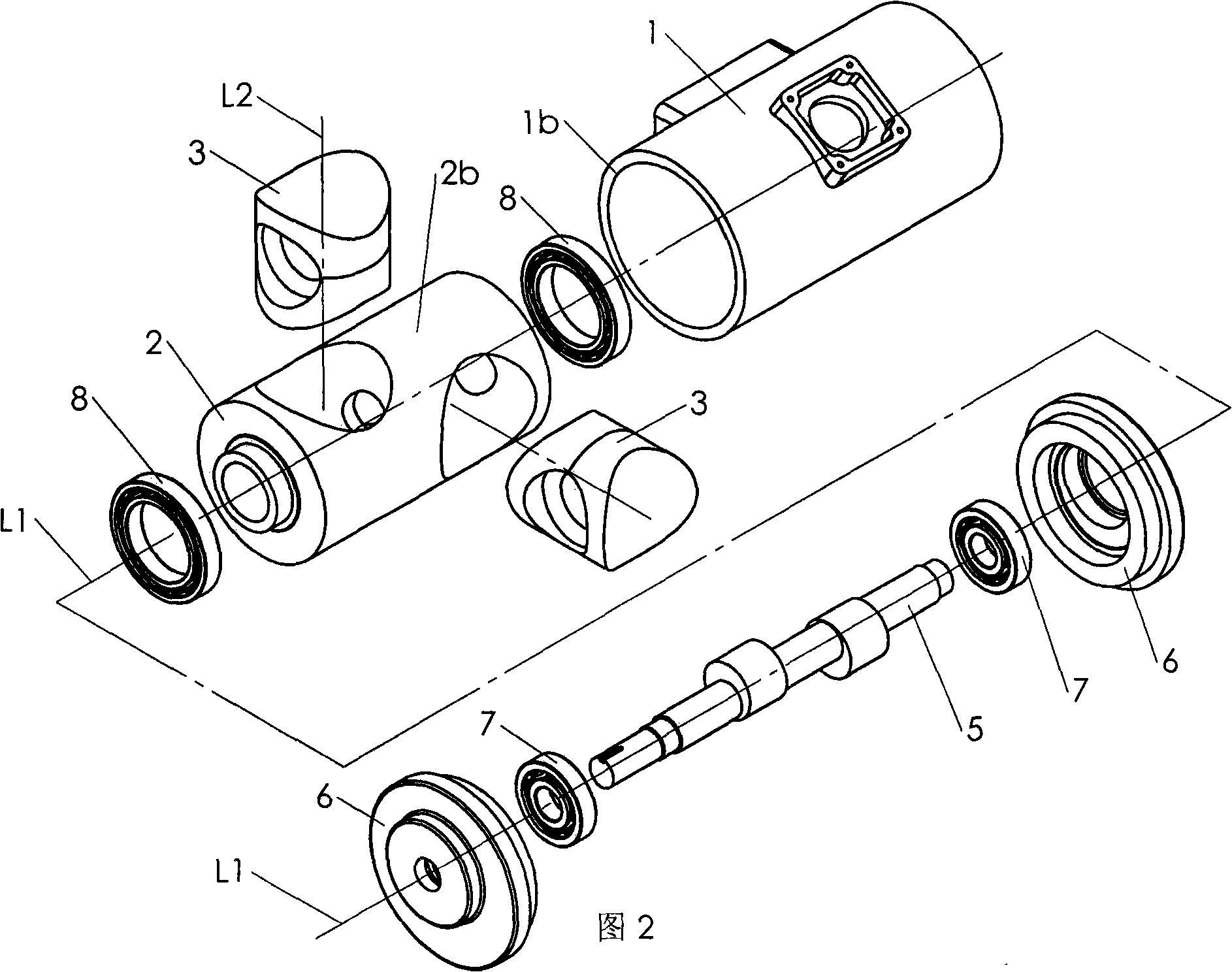
[0030] Fig. 2 is a schematic diagram ...


PUM


Abstract

The invention relates to Carroll fluid machinery, in particular discloses a cylinder dynamic sealing device used in Carroll fluid machinery. The cylinder dynamic sealing device comprises a ring groove (2a) arranged on an outer cylindrical surface (2b) of a rotating cylinder block body (2) matched with the inner hole (1b) of a shell (1) and a sealing ring (4) arranged in the ring groove (2a), and is characterized in that: the ring groove (2a) is arranged closely around the outer periphery of the opening of the cylinder; a special contour line (2d) formed by the intersection of the ring groove (2a) and the outer cylindrical surface (2b) of the rotating cylinder block body (2) and an intersection line (2c) of the outer cylindrical surface (2b) of the rotating cylinder block body (2) of the corresponding cylinder opening have similar special shapes; the sealing ring (4) and the ring groove (2a) have the same special shapes and are sliding-fit along the depth direction of the ring groove (2a). Compared with the traditional Carroll fluid machinery, the invention can substantially reduce circumferential leakage of the medium transmitted in a working cavity at the cylinder opening through the matched gap between the rotating cylinder block and the shell, thereby improving the capacity efficiency and thermal efficiency of the fluid machinery.

Description

technical field [0001] The invention relates to a Carroll fluid machine, in particular to a cylinder dynamic sealing device for a Carroll fluid machine. Background technique [0002] The article "Compressor Uses New Rotary Principle [Document 1]" in the fourth issue of the Canadian magazine "Design Engineering" published in 1973 introduced a new type of compressor for the first time in the world. It was proposed by Robert Karol, and further developed by Richard Ansdale, a famous British rotating machinery expert, and a prototype was manufactured by the British Well-worthy company. This new type of compressor is mainly composed of a rotating cylinder block with a spherical outer peripheral surface, a matching shell with a spherical inner surface that can be split up and down, two cylindrical pistons with spherical end faces, and a cylinder with two The main shaft of an eccentric wheel, and the end covers and bearings on both sides; on the rotating cylinder block, there are t...

Claims


Application Information

Patent Timeline
Patent Type & Authority Applications(China)
IPC IPC(8): F04B39/00F04B27/04
Inventor 高秀峰郁永章魏进家冯诗愚顾兆林
Owner XI AN JIAOTONG UNIV
Why Eureka
Try Eureka