
Forming Head and Process for the Production of a Non-Woven Fabric

a non-woven fabric and forming head technology, applied in the field of fabric production, can solve the problems of increased machine complication and expenditure, inability to use processes and apparatuses, and low production efficiency, and achieve the effect of greater fibre opening capacity

Inactive Publication Date: 2008-10-02
GLATFELTER FALKENHAGEN GMBH
View PDF6 Cites 15 Cited by
  • Summary
  • Abstract
  • Description
  • Claims
  • Application Information

AI Technical Summary

Benefits of technology

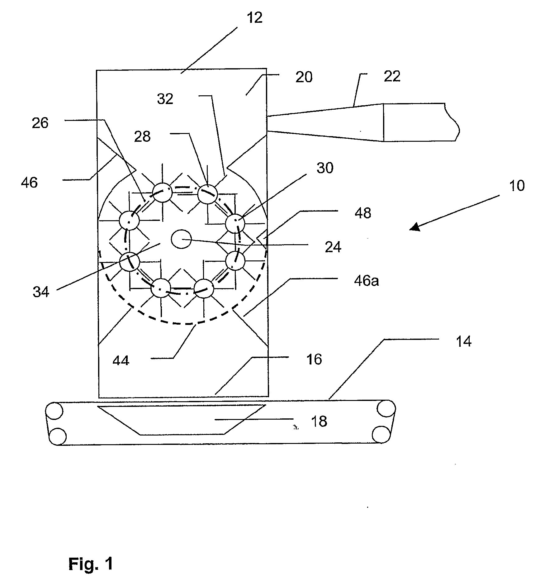
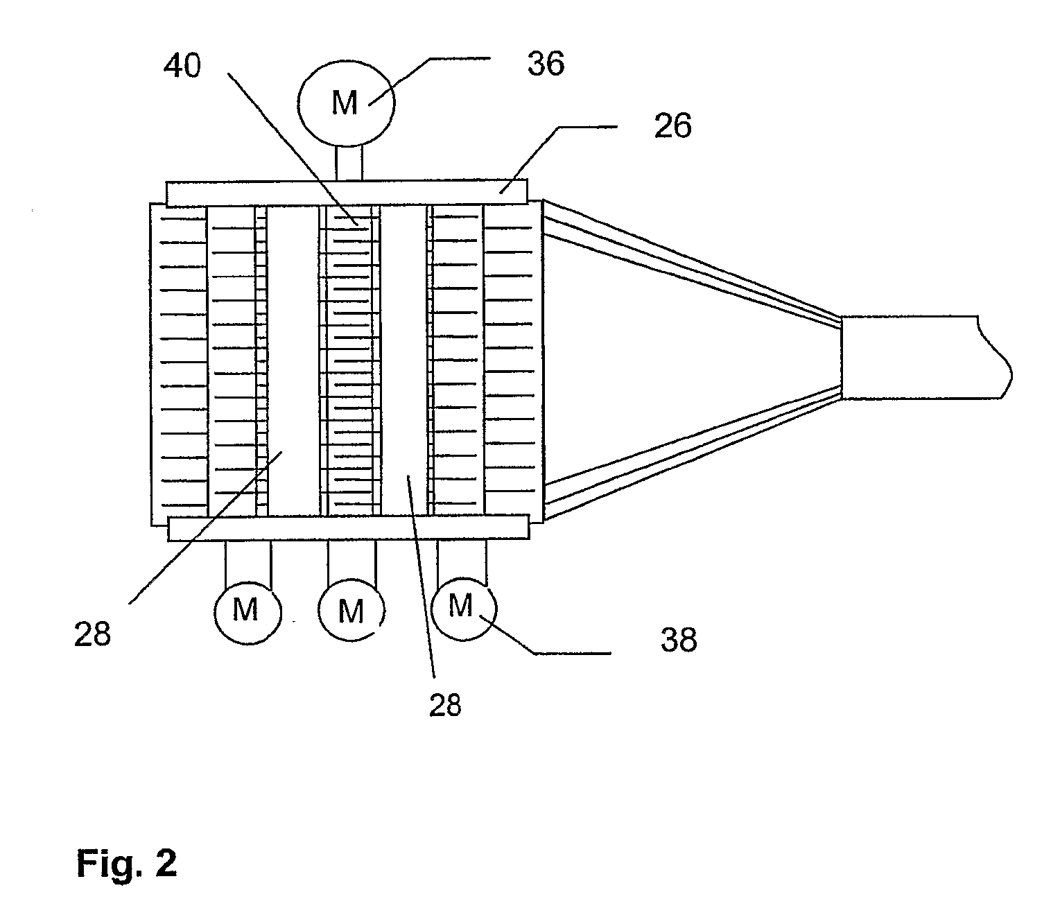
[0019]When using longer fibres of a length of 10 to 60 mm, the sieve is preferably formed by sieve bars which extend at least approximately parallel to each other and to the longitudinal axes of the needle rollers and which are preferably of a round cross-section. The cross-section of the sieve bars is preferably so selected that, in diameter, it corresponds approximately to half the fibre length of the longest fibres to be processed. The spacing of the sieve bars from each other also preferably corresponds to half the fibre length of the longest fibres to be processed. A sieve of that kind acts as a diffuser in the aerodynamic sense and thus contributes to making the air flow uniform within the inner chamber. Thus, for a fibre bed deposited on the conveyor belt, that affords a uniform air flow between the fibre feed means for the fibres to be processed, and the suction box beneath the conveyor belt.

Problems solved by technology

The range of variations in the products which can be produced with conventional apparatuses and processes is usually restricted by virtue of the fact that only given kinds of fibres or fibre lengths are to be processed therewith, so that the known processes and apparatuses cannot be used to produced non-woven fabrics which contain both relatively short fibres and also relatively long fibres, in one forming step.
Disadvantages here are the increased level of machine complication and expenditure and the low weights in relation to surface area which can be achieved, if the fibres are provided by way of a carding process.

Method used


Image

  • Forming Head and Process for the Production of a Non-Woven Fabric
  • Forming Head and Process for the Production of a Non-Woven Fabric

Examples


Embodiment Construction

[0027]The installation 10 shown in FIG. 1 for the production of a non-woven fabric includes a forming head 12 arranged above a conveyor belt 14. The conveyor belt 14 is air-permeable. The forming head 12 has a lower deposit opening 16 above the conveyor belt 14. A suction box 18 is arranged beneath the conveyor belt 14 and beneath the deposit opening 16.

[0028]A directed air flow can be produced by means of the suction box 18 through the forming head 12, out of the deposit opening 16, through the conveyor belt 14, and into the suction box 18.

[0029]Fibres which are deposited on the conveyor belt 14 by the forming head 12 can be securely sucked on to the conveyor belt 14 by means of the air flow. Fibres deposited on the conveyor belt 14 by the forming head 12 form a fibre bed (not shown) on the conveyor belt 14. By virtue of the fact that the conveyor belt 14 is continuously driven in circulation, a continuous fibre bed can be produced on the conveyor belt 14 if fibres are at the same ...


PUM

PropertyMeasurementUnit
lengthaaaaaaaaaa
lengthaaaaaaaaaa
lengthsaaaaaaaaaa

Abstract

The invention concerns a forming head for an apparatus for the production of a non-woven fabric by depositing fibres on a conveyor belt, comprising a fibre feeder which opens into a fibre processing chamber and which has a lower deposit opening for the delivery of fibres, wherein arranged in the fibre processing chamber are interengaging needle rollers with longitudinal axes oriented in mutually parallel relationship, which can rotate about their respective longitudinal axis, and the interengaging needle rollers enclose an inner chamber and are arranged with respect to the fibre feeder and the deposit opening in such a way that fibres fed to the forming head in operation enter the inner chamber by passing through between interengaging needle rollers and leave the inner chamber also by passing through between interengaging needle rollers.

Description

CROSS REFERENCE TO RELATED APPLICATIONS[0001]This application is for entry into the U.S. national phase under §371 for International Application No. PCT / EP05 / 051971 having an international filing date of Apr. 29, 2005, and from which priority is claimed under all applicable sections of Title 35 of the United States Code including, but not limited to, Sections 120, 363 and 365(c), and which in turn claims priority under 35 USC §119 to German Patent Application No. DE 10 2004 021 453.0-26 filed on Apr. 29, 2004.BACKGROUND OF THE INVENTION[0002]1. Technical Field[0003]The invention concerns the production of fabric, and more particularly, the production of non-woven fabric.[0004]2. Discussion of Related Art[0005]The invention concerns on the one hand a forming head for an apparatus for the production of a non-woven fabric and on the other hand a process for processing fibres for the production of a non-woven fabric. The forming head has at least one fibre feed means which opens into a ...

Claims


Application Information

Patent Timeline
Patent Type & Authority Applications(United States)
IPC IPC(8): B29B15/00D02G1/20D04H1/00B27N3/14D04H1/425D04H1/4258D04H1/4291D04H1/435D04H1/492D04H1/541D04H1/552D04H1/64D04H1/70D04H1/72D04H1/732
CPCD04H1/425D04H1/4258D04H1/4291D04H1/435D04H1/492D04H1/541D04H1/552D04H1/64D04H1/70D04H1/72D04H1/732D04H18/02Y10T442/60D04H1/5412D04H1/5418
Inventor NORGAARD, RAYMONDHANSEN, MORTEN RISE
Owner GLATFELTER FALKENHAGEN GMBH
Learn More