Intervertebral Device Having Expandable Endplates

a technology of endplates and intervertebral devices, which is applied in the field of intervertebral devices having expandable endplates, can solve the problems of low back pain, inability to reduce the size of the prosthetic endplate, and the low profile, so as to increase the footprint of the implant endplate, increase the stability of the implant, and reduce the profil

Active Publication Date: 2008-10-02
DEPUY SYNTHES PROD INC
View PDF13 Cites 147 Cited by
  • Summary
  • Abstract
  • Description
  • Claims
  • Application Information

AI Technical Summary

Benefits of technology

[0011]In a first embodiment, the endplate comprises a pair of planks that are slidably received within respective recesses of a base portion of the endplate. During insertion of the implant into the intervertebral space, the planks are set in a contracted position within respective recesses of a base portion of th...

Problems solved by technology

The leading cause of lower back pain arises from rupture or degeneration of lumbar intervertebra...

Method used


Image

  • Intervertebral Device Having Expandable Endplates
  • Intervertebral Device Having Expandable Endplates
  • Intervertebral Device Having Expandable Endplates

Examples


Embodiment Construction

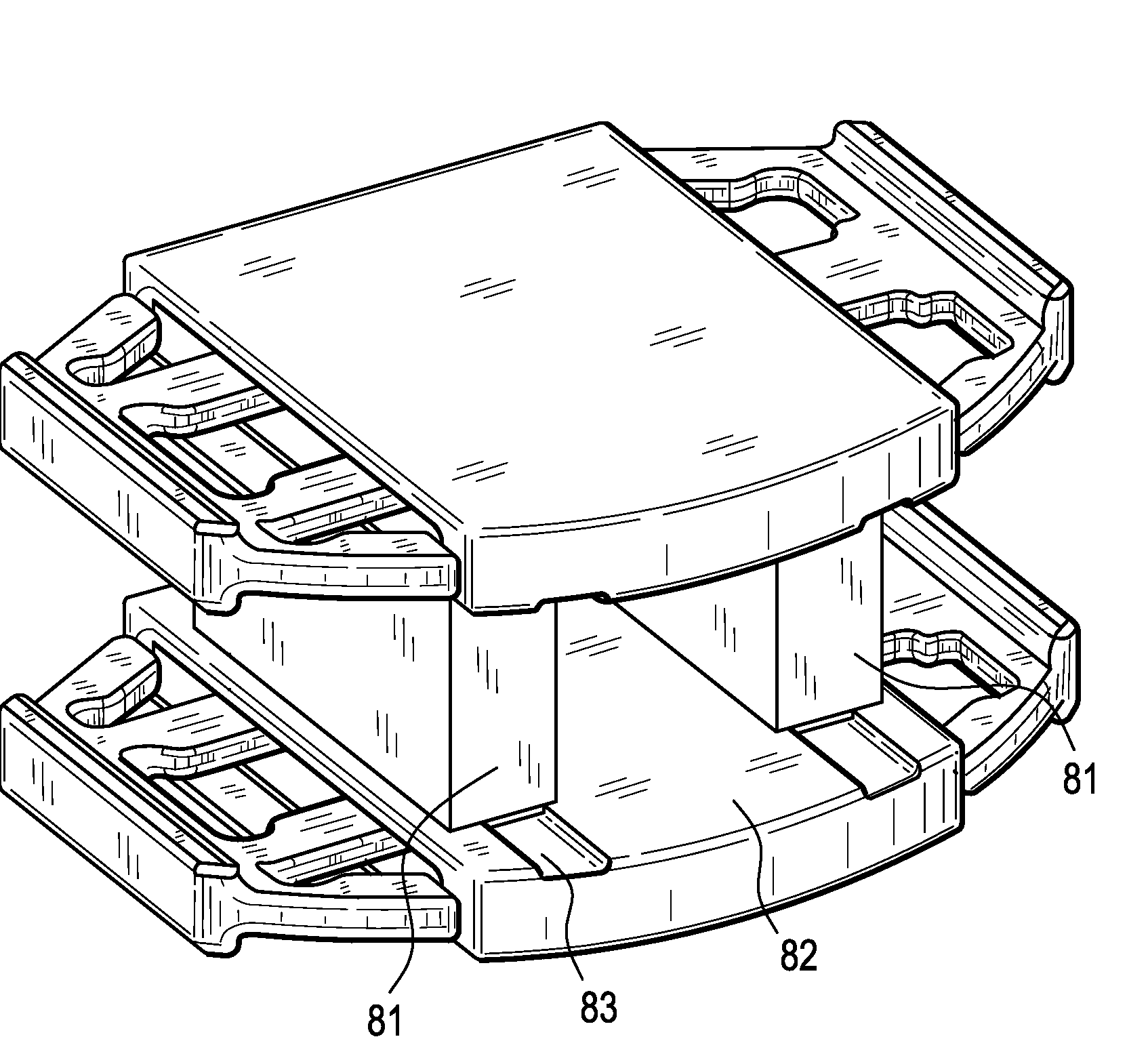
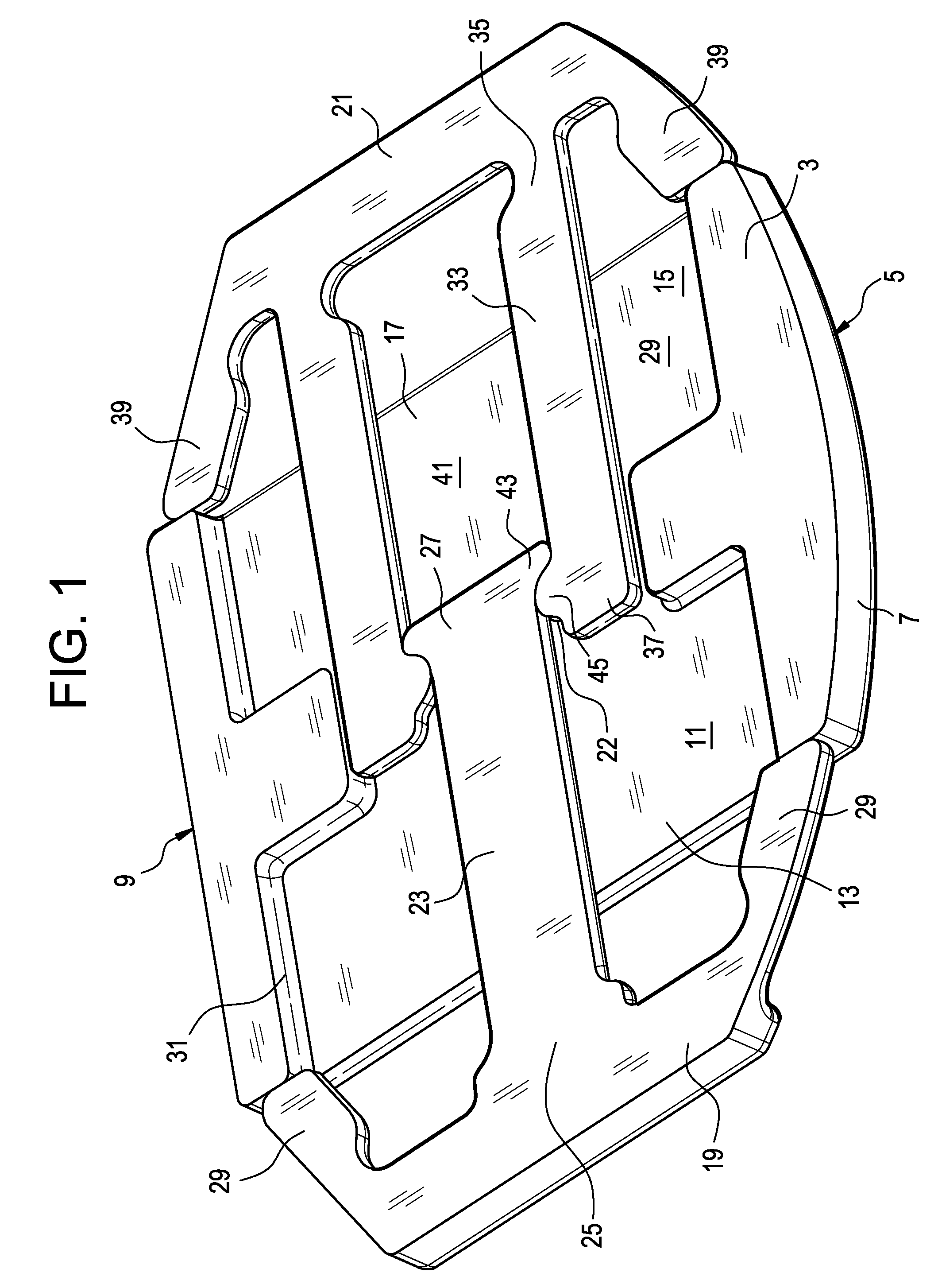
[0025]Now referring to FIG. 1, there is provided an intervertebral prosthetic device having an expandable endplate, comprising:[0026]a) a first base portion 1 having an outer surface 3 adapted for bearing against a natural endplate, an inner surface 5, first 7 and second 9 side surfaces extending between the outer and inner surfaces, a first cutout 11 opening onto the outer surface and the first side surface and forming a first recessed surface 13, and a second cutout 15 opening onto the outer surface and the second side surface and forming a second recessed surface 17,[0027]b) a first plank 19 slidingly receivable within the first cutout and adapted to translate across the first recessed surface, and[0028]c) a second plank 21 slidingly receivable within the second cutout and adapted to translate across the second recessed surface.

[0029]In this embodiment, the first and second cutouts are joined by a third recessed surface 22 in the outer surface of the first base portion.

[0030]The ...


PUM

PropertyMeasurementUnit
Angleaaaaaaaaaa
Flexibilityaaaaaaaaaa
Shapeaaaaaaaaaa

Abstract

An intervertebral implant having an endplate that can be slidably expanded following its placement in the intervertebral space.

Description

BACKGROUND OF THE INVENTION[0001]The leading cause of lower back pain arises from rupture or degeneration of lumbar intervertebral discs. Pain in the lower extremities is caused by the compression of spinal nerve roots by a bulging disc, while lower back pain is caused by collapse of the disc and by the adverse effects of articulation weight through a damaged, unstable vertebral joint. One proposed method of managing these problems is to remove the problematic disc and replace it with a prosthetic disc that allows for the natural motion between the adjacent vertebrae (“a motion disc”).[0002]Since first generation motion discs were inserted anteriorly, the size of the disc's endplate did not hinder the insertion technique and so was essentially equal to the size of the vertebral endplates opposing the motion disc. However, later generation motion discs seek to insert the motion disc from the posterior or posterolateral directions. These methods of insertion seek to minimize the size ...

Claims


Application Information

Patent Timeline
IPC IPC(8): A61F2/44A61B17/58
CPCA61F2/441A61F2/442A61F2/4455A61F2002/30151A61F2002/3037A61F2002/30383A61F2002/30471A61F2002/30476A61F2002/30579A61F2002/30604A61F2220/0025A61F2220/0033A61F2220/0091A61F2230/0017A61F2/4425
Inventor STAD, SHAWNRAMSAY, CHRISTOPHER
Owner DEPUY SYNTHES PROD INC
Why Eureka
Try Eureka