
Rotational apparatus for welding beam-mount structure to the side(s) of a column

a technology of rotating apparatus and beam-mount structure, which is applied in the direction of girders, manufacturing tools, joists, etc., can solve the problems of deformation, difficult to correct or manage, and difficult to blam

Active Publication Date: 2008-10-09
CONXTECH INC
View PDF7 Cites 13 Cited by
  • Summary
  • Abstract
  • Description
  • Claims
  • Application Information

AI Technical Summary

Benefits of technology

The present invention relates to a building frame structure and an apparatus for efficiently and precisely placing beam mounts on tubular steel columns in a building frame. The invention addresses challenges associated with manufacturing and assembly of building frames using hollow tubular columns, such as heat-induced deformation and difficulty in achieving precise column alignment. The invention offers an off-site solution for preparing columns with beam mounts, and can be controlled using computer and robotics. The apparatus includes a jig for supporting and shifting a column, and a plurality of end stands carrying idler support rollers for precise positioning of beam mounts. The invention enables non-heat-deforming and precise deployment of beam mounts to the outer sides of columns, which can be difficult to achieve using conventional welding methods.

Problems solved by technology

Such columns, however, can present challenges during manufacture, and later during assembly with beams, regarding which (in both cases) there are manufacturing and assembling steps wherein it is conventional that high heat (due to welding operations) is (or may be) involved.
Such heat can prove to be a difficult culprit (a) during manufacture where a column can warp or twist (even slightly) during cool-down, and (b) during building-frame assembly where extreme local hot regions created during welding operations can introduce similar undesirable, and often difficult to correct or manage, deformations.

Method used


Image

  • Rotational apparatus for welding beam-mount structure to the side(s) of a column
  • Rotational apparatus for welding beam-mount structure to the side(s) of a column
  • Rotational apparatus for welding beam-mount structure to the side(s) of a column

Examples


Embodiment Construction

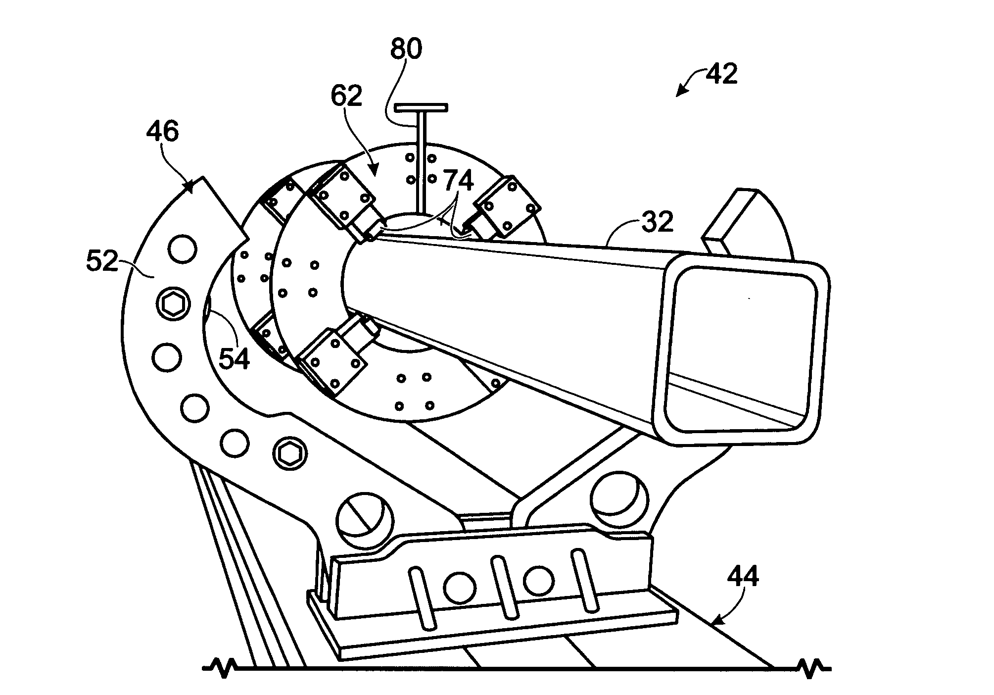
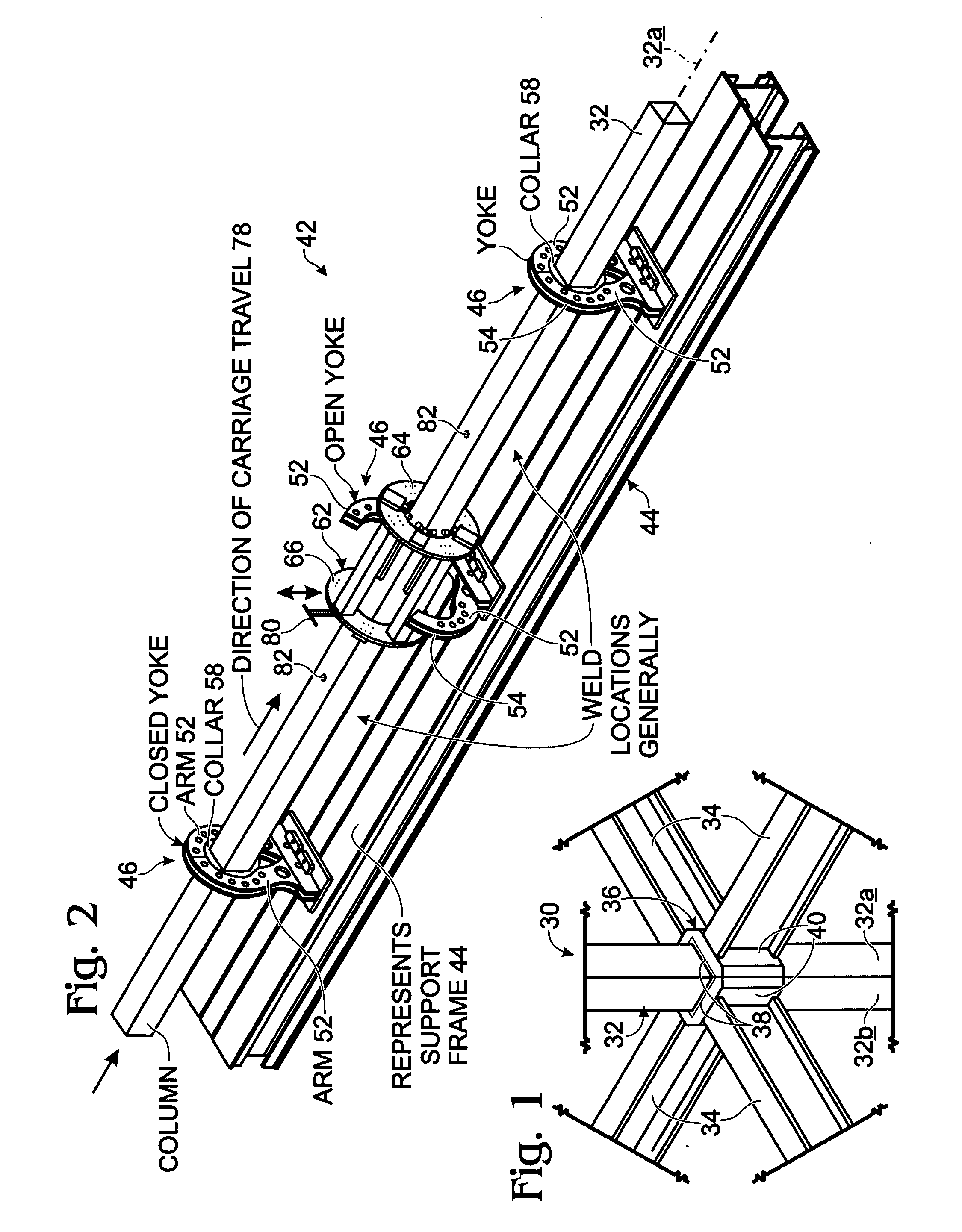
[0036]Turning now to the drawings, and referring first of all to FIG. 1, illustrated fragmentarily and generally, and also in a somewhat simplified form, at 30 in this figure are portions of a precision, close-tolerance structural building frame which has been constructed in accordance with the teachings of above-referred-to U.S. Pat. No. 6,837,016. Frame structure 30 includes upright tubular, square cross section elongate steel columns, such as the single column shown at 32, two orthogonally related outside faces of which are seen in FIG. 1 at 32a, 32b.

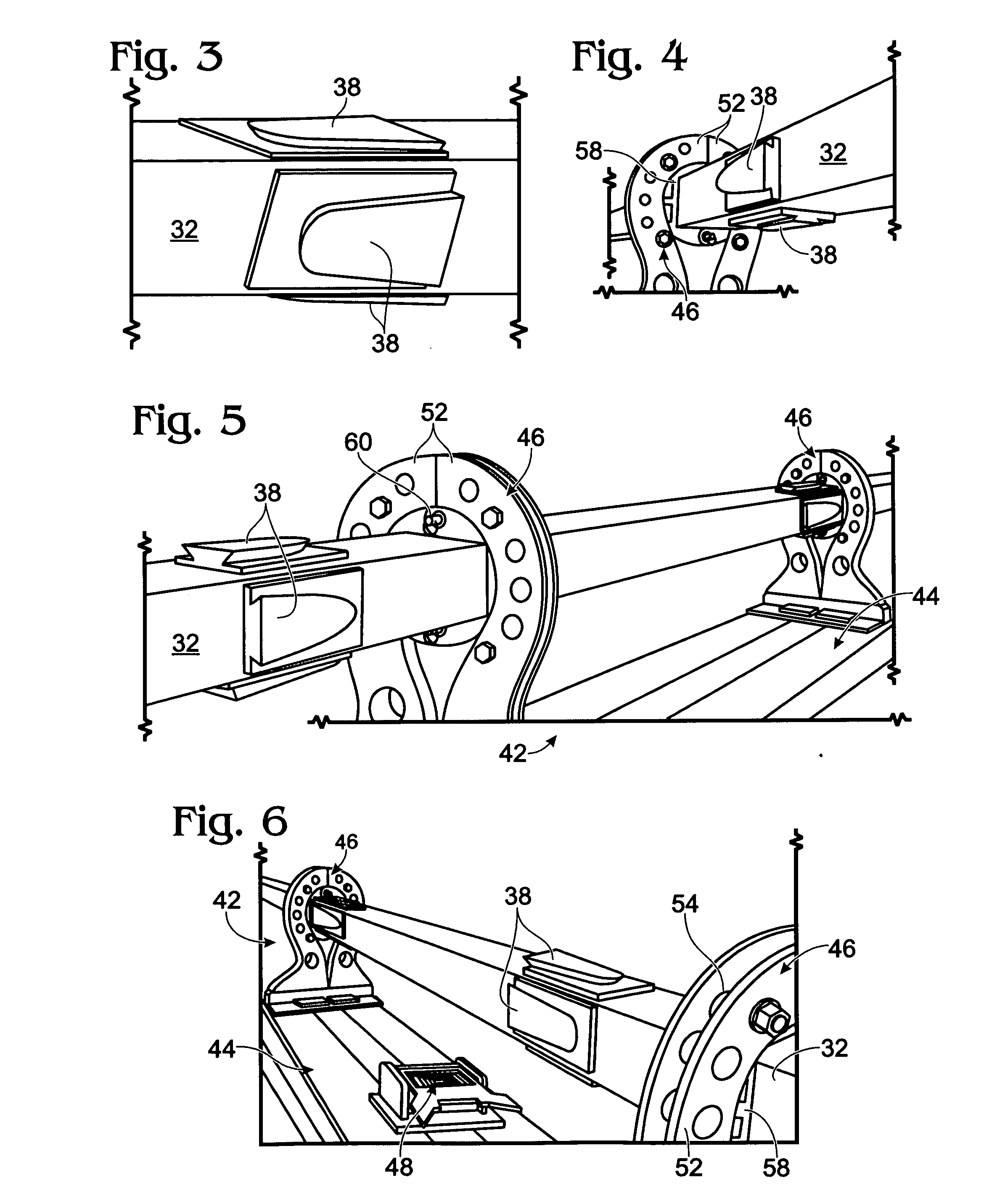
[0037]Joined to the four orthogonally related faces, such as faces 32a, 32b, in column 32 are the ends of four horizontal I-beams, such as those shown at 34, with these I-beams being joined to column 32 through a style of collar interconnect structure 36 which has been constructed in accordance with the teachings of the referenced '016 patent. More specifically, collar interconnect structure 36 is made up of a cluster of four column...


PUM

PropertyMeasurementUnit
angleaaaaaaaaaa
lengthaaaaaaaaaa
lengthsaaaaaaaaaa

Abstract

Apparatus for precision deploy-attaching beam-mount structure to the outside of an elongate column at plural, defined attachment sites that are distributed and spaced along the length of the column. During use, a column support jig with plural openable / closeable yokes in the apparatus supports a column horizontally for selective rotation about its long axis. A carriage in the apparatus, which holds beam-mount structures to be attached to a supported column, is selectively moveable and position-lockable in defined locations distributed along the supported column between yokes in a pair of spaced yokes to enable precision weld-attaching of the mounts to sides of the column.

Description

CROSS REFERENCES TO RELATED APPLICATIONS[0001]This application is a Division of U.S. patent application Ser. No. 10 / 938,909, filed Sep. 9, 2004, for “Rotational Method and Apparatus for Welding Beam-Mount Structure to the Sides of a Column”, which application claims priority to the filing date of U.S. Provisional Patent Application Ser. No. 60 / 503,071, filed Sep. 14, 2003 for “Rotational Method and Apparatus for Welding Beam-End Attaching Components to the Side of a Column”. The contents of those prior-filed, U.S. patent applications are hereby incorporated herein by reference.BACKGROUND AND SUMMARY OF THE INVENTION[0002]This invention pertains to building frame structure, and in particular to an apparatus for performing precision-placement, and deployment-attaching and welding, of plural beam-end attaching components, referred to also herein as beam mounts, and as beam-mount structure, to plural spaced regions, or sites, that are distributed along the outer sides of elongate, hollo...

Claims


Application Information

Patent Timeline
Patent Type & Authority Applications(United States)
IPC IPC(8): E04B5/10B23K31/12E04B1/24E04B1/26
CPCB23K31/12Y10T29/49634E04B1/26E04B5/10E04B2001/2415E04B2001/2454Y10T29/53996Y10T29/53543Y10T29/53961Y10T29/53539Y10T29/53548Y10T403/348Y10T29/53Y10T403/341B23K2201/28B23K2101/28
Inventor SIMMONS, ROBERT J.
Owner CONXTECH INC
Learn More