Flat Tube Making Platelike Body, Flat Tube, Heat Exchanger and Process for Fabricating Heat Exchanger

a technology of heat exchanger and flat tube, which is applied in the direction of tubular elements, stationary conduit assemblies, reinforcement means, etc., can solve the problems of increasing the above problem, increase and improve the pressure resistance of flat tubes. , the effect of increasing the area of brazing

Inactive Publication Date: 2008-10-09
SHOWA DENKO KK
View PDF7 Cites 5 Cited by
  • Summary
  • Abstract
  • Description
  • Claims
  • Application Information

AI Technical Summary

Benefits of technology

[0043]When the platelike body described in par. 9) is used, the two reinforcing wall forming portions can be given an increased area of brazing between the two reinforcing wall forming portions, entailing the greater advantage of giving an increased brazing joint strength to the two portions and further improved pressure resistance to the flat tube as already described with reference to par. 1).
[0044]The advantage described with reference to par. 10) is available to a greater extent with the platelike body according to par. 9).
[0045]When the platelike body described in par. 11) is used, the two reinforcing wall forming portions can be given an increased area of brazing between the two reinforcing wall forming portions, entailing the greater advantage of giving an increased brazing joint strength to the two portions and further improved pressure resistance to the flat tube as already described with reference to par. 1).
[0046]When the platelike body described in par. 12) is used, the two reinforcing wall forming portions can be given an increased area of brazing between the two reinforcing wall forming portions, entailing the greater advantage of giving an increased brazing joint strength to the two portions and further improved pressure resistance to the flat tube as already described with reference to par. 1).
[0047]The flat tube according to par. 13) and 16) has enhanced brazing joint strength between the two reinforcing wall forming portions, and tube is therefore given improved pressure resistance.
[0048]In the case of the heat exchanger according to par. 17), the flat tubes can be given sufficient pressure resistance even if diminished in weight or size. This renders the heat exchanger smaller in size and lightweight in its entirety

Problems solved by technology

However, the flat tube making platelike body disclosed in the above publication is found to have the following problem because the corresponding pair of reinforcing wall forming portions on the flat wall forming portions are equal in thickness.
Although it appear useful to make the refrigerant tube, for example, 16 mm in width, 1.1 mm in height and up to about 0.5 mm in the wall thickness of the reinforcing wall forming portions in order to provide a compacted condenser, the above problem becomes pronounced in such a case.

Method used


Image

  • Flat Tube Making Platelike Body, Flat Tube, Heat Exchanger and Process for Fabricating Heat Exchanger
  • Flat Tube Making Platelike Body, Flat Tube, Heat Exchanger and Process for Fabricating Heat Exchanger
  • Flat Tube Making Platelike Body, Flat Tube, Heat Exchanger and Process for Fabricating Heat Exchanger

Examples


Embodiment Construction

[0065]Embodiments of the present invention will be described below with reference to the drawings. In the following description, the upper and lower sides, and the left- and right-hand sides of FIG. 1 will be referred to as “upper,”“lower,”“left” and “right,” respectively. Throughout the drawings, like parts will be designated by like reference numerals.

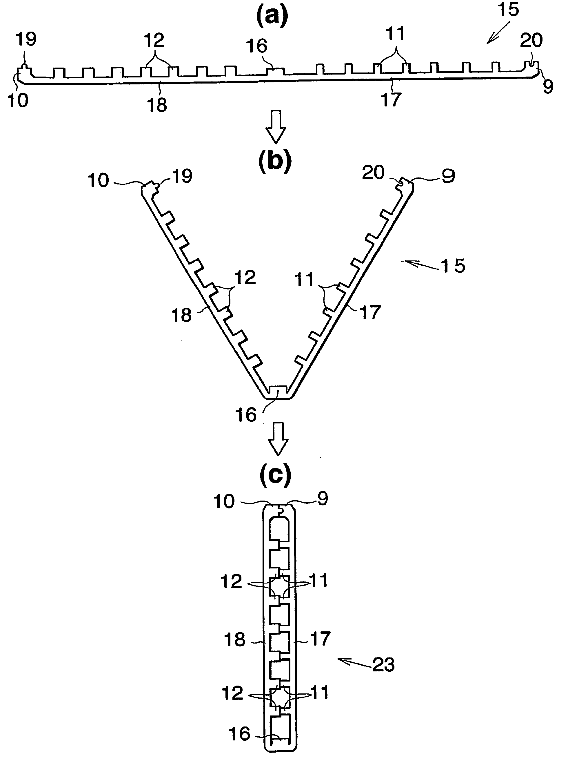
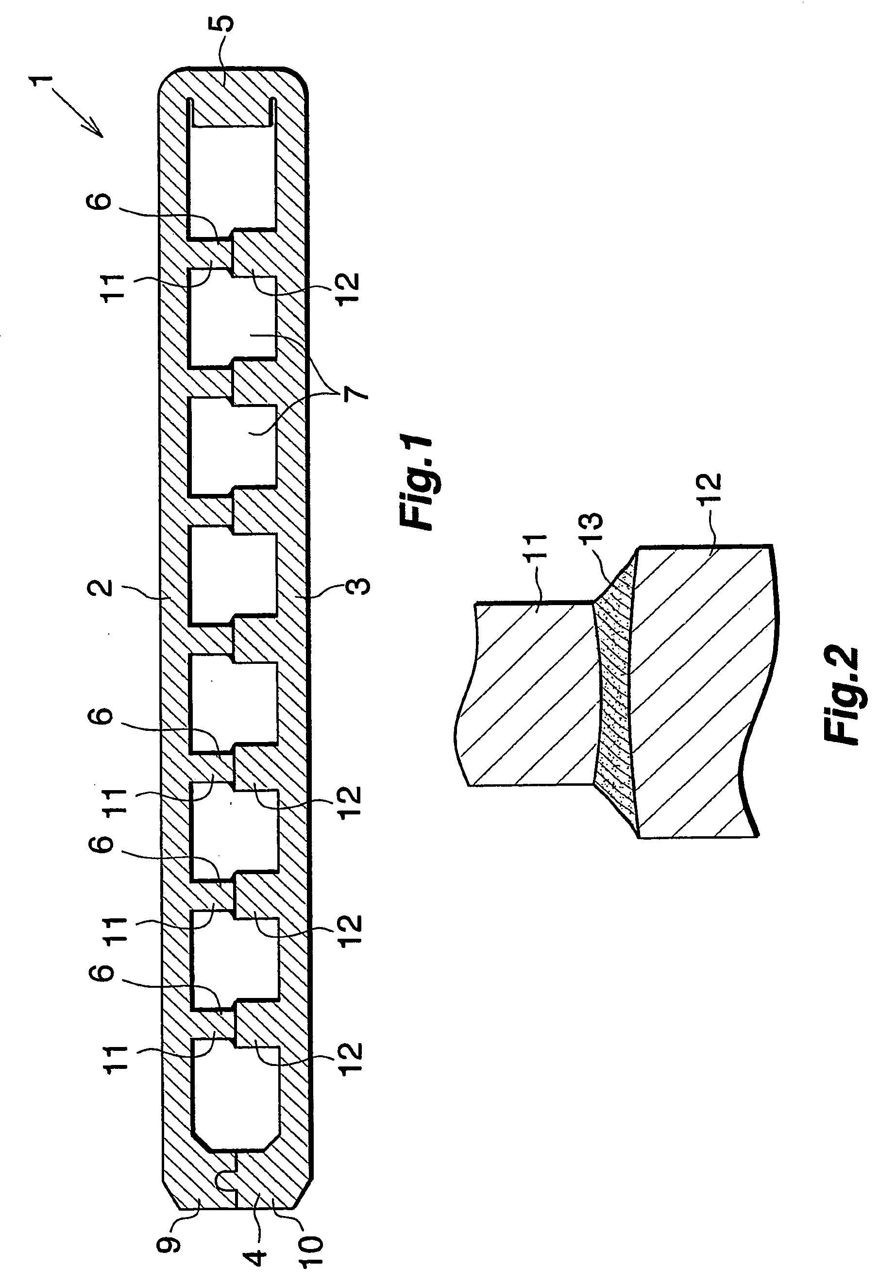
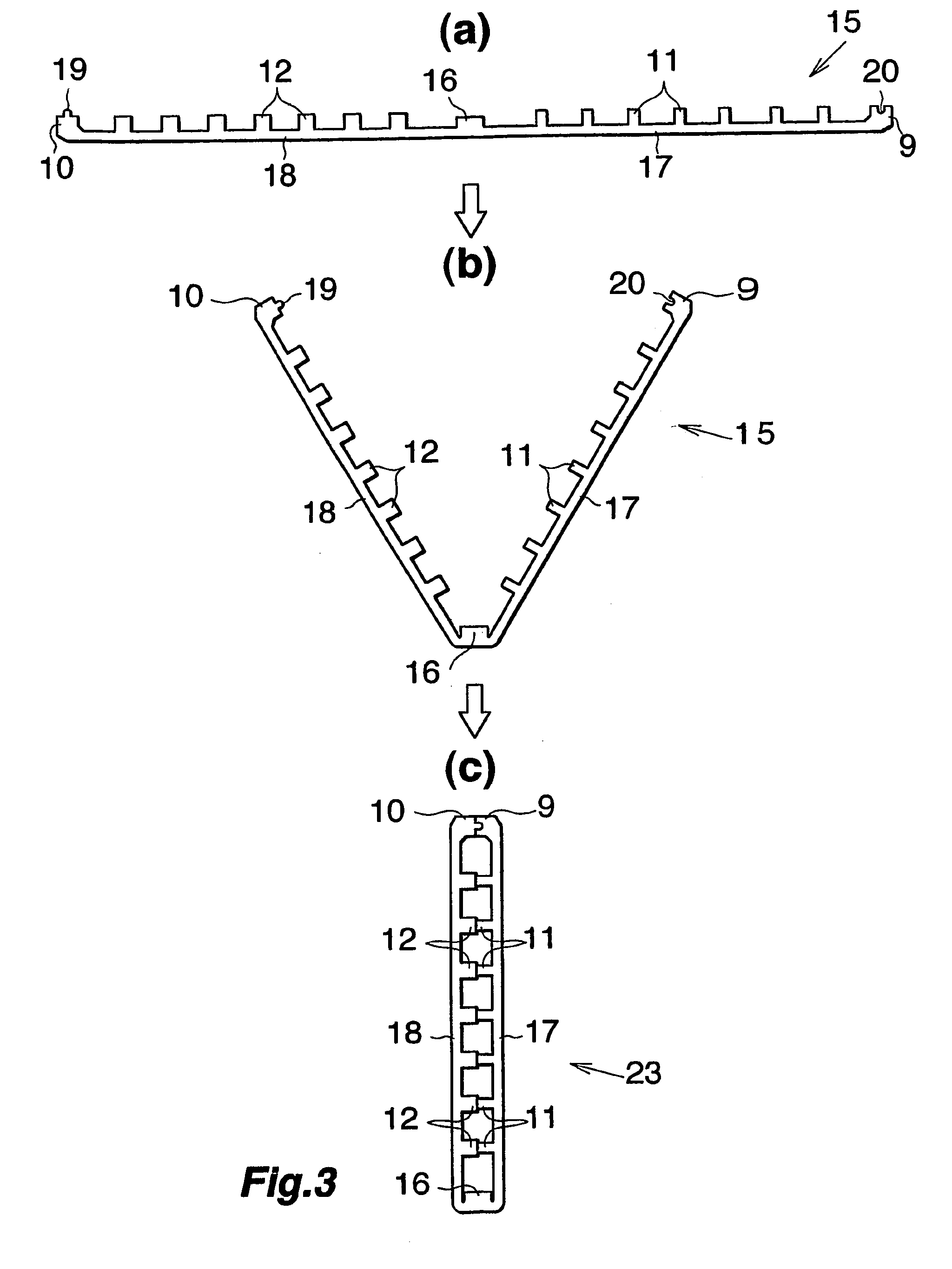
[0066]FIG. 1 shows a flat tube, FIG. 2 is a fragmentary view of the flat tube, FIG. 3 shows some steps of a process for fabricating the flat tube using a platelike body, and FIG. 4 is a fragmentary view of FIG. 3(c).

[0067]With reference to FIG. 1, the flat tube 1 is made of aluminum and comprises an upper and a lower flat wall 2, 3 (a pair of flat walls) opposed to each other, left and right opposite side walls 4, 5 interconnecting the upper and lower walls 2, 3 at left and right opposite side edges thereof, and a plurality of reinforcing walls 6 interconnecting the upper and lower walls 2, 3, extending longitudinally of the tube and...


PUM


Abstract

A flat tube making platelike body 15 is in the form of a single metal plate in its entirety and comprises two flat wall forming portions 17, 18 having the same width, a connecting portion 16 for interconnecting these portions 17, 18, side wall forming portions 9, 10 projecting from the respective flat wall forming portions 17, 18 and each formed integrally with one side edge of the flat wall forming portion opposite to the connecting portion 16, and first and second reinforcing wall forming portions 11, 12 integrally formed on each of the flat wall forming portions 9, 10. The first reinforcing wall forming portions 11 are butted against the respective second reinforcing wall forming portions 12 in pairs when the metal plate is folded into a hairpin form at the connecting portion 16. The first reinforcing wall forming portions 11 are given a smaller thickness than the second reinforcing wall forming portions 12 on the other flat wall forming portion 18 butted against the respective portions 11. The platelike body 15 gives an enhanced brazing joint strength to the reinforcing wall forming portions in fabricating a flat tube, and improved pressure resistance to the flat tube to be fabricated.

Description

CROSS REFERENCE TO RELATED APPLICATION[0001]This application is an application filed under 35 U.S.C. §111(a) claiming the benefit pursuant to 35 U.S.C. §119(e)(1) of the filing date of Provisional Application No. 60 / 559,950 filed Apr. 7, 2004 pursuant to 35 U.S.C. §111(b).TECHNICAL FIELD[0002]The present invention relates to platelike bodies useful for making flat tubes for use as heat exchange tubes for heat exchangers, such as refrigerant tubes in condensers or evaporators for motor vehicle air conditioners, oil tubes for motor vehicle oil coolers, water tubes for motor vehicle radiators and heat medium tubes for heater cores, flat tubes, heat exchangers comprising such flat tubes and a process for fabricating the exchanger.[0003]The term “aluminum” as used herein and in the appended claims includes aluminum alloys in addition to pure aluminum.BACKGROUND ART[0004]In recent years, widely used in motor vehicle air conditioners in place of conventional serpentine condensers are conde...

Claims


Application Information

Patent Timeline
Patent Type & Authority Applications(United States)
IPC IPC(8): F28F1/00B21D53/04F28F1/02
CPCF28D1/0391F28F3/048F28F2225/04
Inventor KAIMURA, SATORUKAMEDA, MAKOTOTANAKA, DAISHITAMURA, TAKASHI
Owner SHOWA DENKO KK
Why Eureka
Try Eureka