Unfortunately, there are severe problems and limitations to the laid wire technology.
Laid wire systems run on
high voltage and there is a risk of fire if there is any breakages or discontinuities in the conductive wire.
Laid wire systems are also rendered useless if there is any discontinuity in the conductive element and they have a harsh feel due to the wire being thick and not very
user friendly or aesthetically pleasing and good to touch.
In addition, laid wire systems are characterized by: uneven heating, where the system is designed such that there is
high heat on the wires to compensate for separation between the wires, thereby resulting in localized high heating and assumption that the heat will spread to other regions of the
blanket; the systems are conductively dangerous (e.g., if a child cuts the wire using any device it may be fatal due to
high voltage); the wire system also has all wire loops starting and ending at a termination point; and, there are limitations on the number of zones capable in a laid wire system.
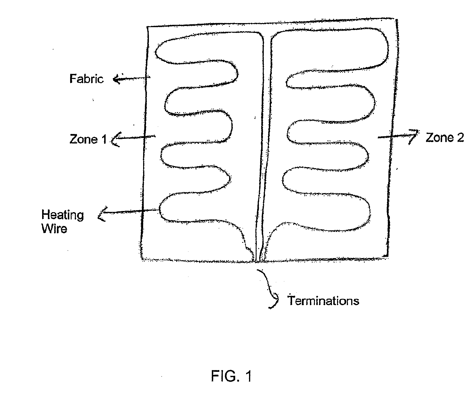
Further, laid wire systems have a limitation on generation of dual zones, where such systems are generated by creating two separate pathways laid down side by side, an example of which is shown by FIG. 1.
Laid wire systems are also limited in that the conductive wire distribution in each zone is limited to being symmetrical, resulting in each zone having the same
layout.
These products are limited in width due to the machines utilized in fabrication and producing wider machines will be extremely cost prohibitive, and not a readily available solution.
There are problems that will be encountered in such an approach.
Unfortunately, since the conductive element is rigid and has low flexibility it will be difficult to increase or generate wider widths, specifically, since more conductor length will cause problems of breakages during
fiber raising processes.
Also, material will be required to be heat set on machines and pulled to generate the width, thereby adding substantial forces on the conductor that will possibly result in breakages.
There are problems that will be encountered in such an approach.
As an example, the conductive element will need to be able to stretch that length, however, since the conductive element is rigid and has low flexibility it will be difficult to increase or generate wider widths and more conductor length will cause problems of breakages during
fiber raising processes.
Also, material will be required to be heat set on machines and pulled to generate the width, thereby adding substantial forces on the conductor that will possibly result in breakages.
Unfortunately, there are still limitations to the Malden Mills articles, examples of which include at least the following.
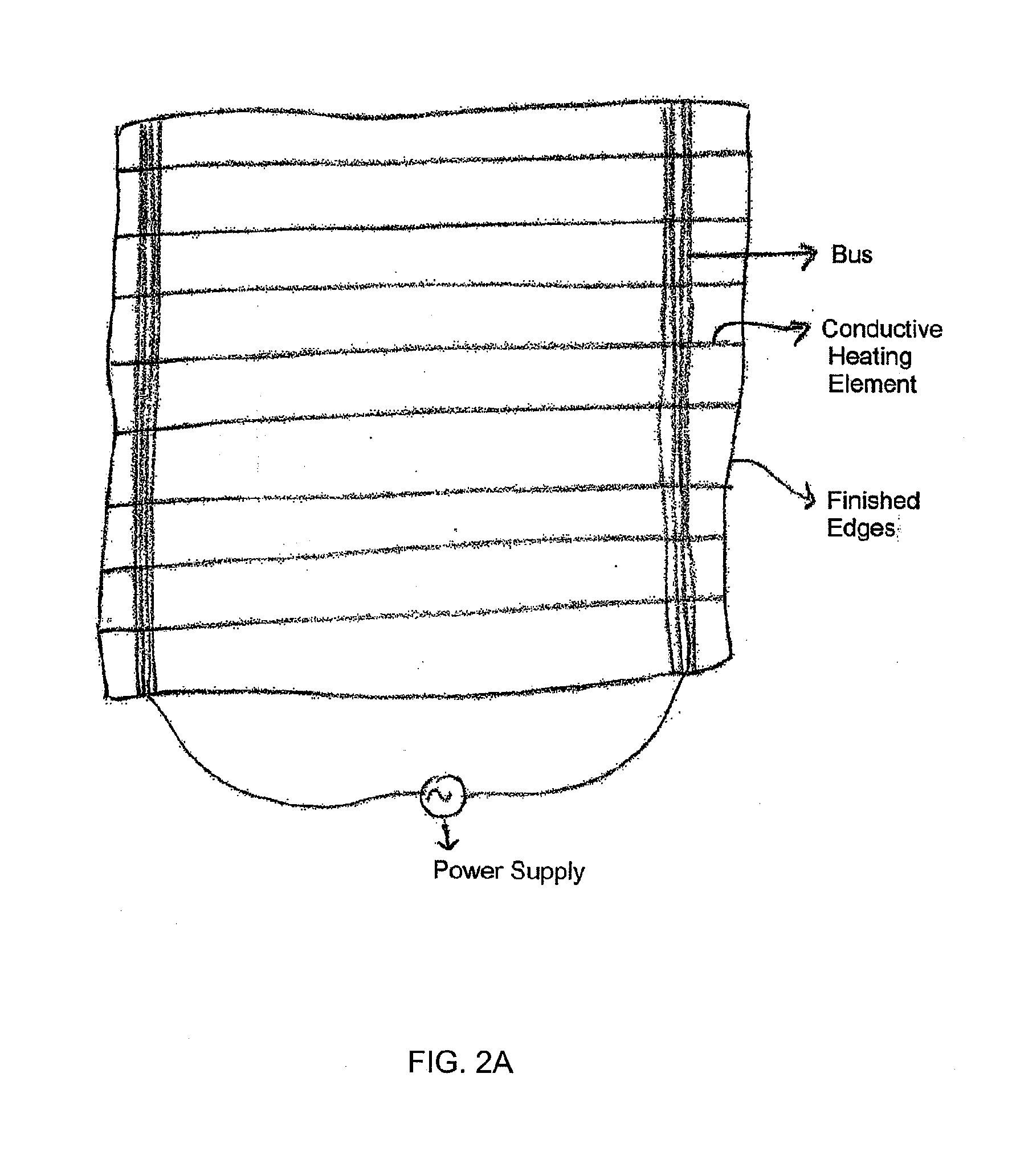
The result of having to mechanically attach the
bus to each conductive element is a limitation of width of the resulting system, a limitation on zone wire configuration, and a limitation in the number of zones.
Unfortunately, for raised fabric surfaces such capabilities are very limited.
Also, wide width would be required for all the machines in the process that
handle the fabric (e.g., nappers, shears, heat setters, etc.), which is a cost prohibitive and
time consuming exercise.
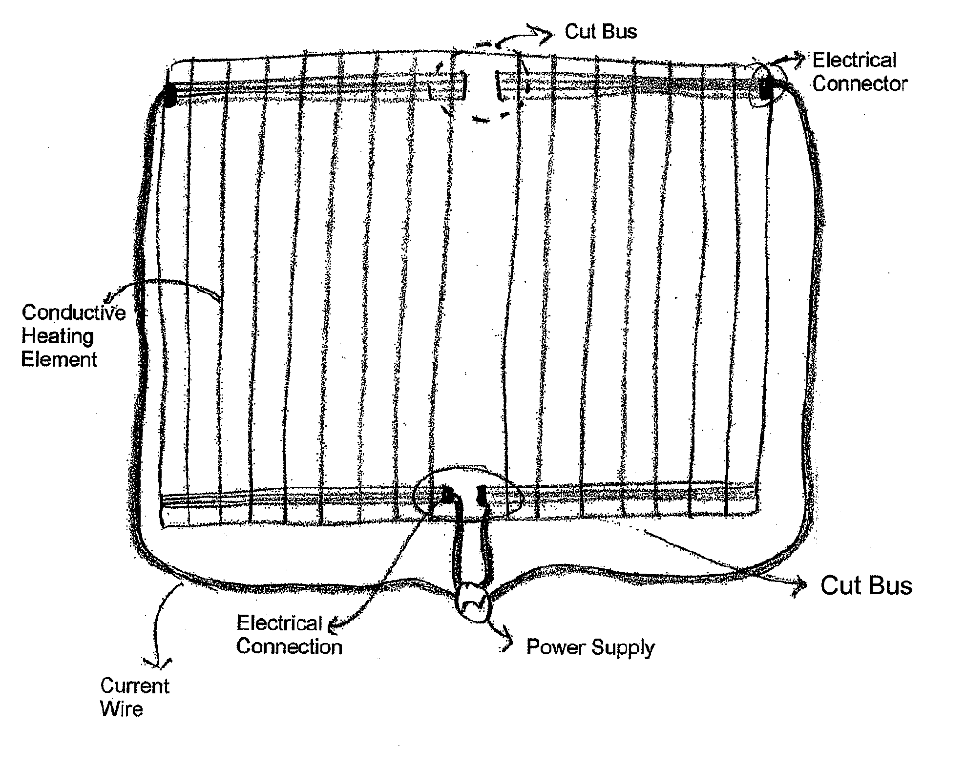
With regard to the limitation on zones, the parallel wire configuration can be configured to create dual zones but it adds additional complexities where connection has to occur on the top
bus and wire has to snake down along the edges into a termination point.
The two top bus termination points require the wire to snake down along the selvedge to the termination box, which is a very inefficient and
time consuming operation and potential to have failures.
Unfortunately, the lamination between
layers results in rigidness and lamination can delaminate with washing.
Thus, a heretofore unaddressed need exists in the industry to address the aforementioned deficiencies and inadequacies.

