
Furniture-glide assembly

Active Publication Date: 2008-10-09
HIWATT PROD
View PDF51 Cites 28 Cited by
  • Summary
  • Abstract
  • Description
  • Claims
  • Application Information

AI Technical Summary

Benefits of technology

[0011]One advantage of the furniture-glide assembly of the present invention is that it provides a relatively efficient way of replacing the existing foot from the free end of the leg of the piece of furniture.
[0031]Another advantage of the furniture-glide assembly of the present invention is that it can be manufactured easily and inexpensively.

Problems solved by technology

However, this type of foot suffers from many disadvantages.
The bottom surface of the conventional foot is relatively large, which increases the amount of frictional contact with the floor and causes scraping and scratching of relatively more surface area of the floor.
And, use of this type of foot generally facilitates a sliding motion across the floor and, therefore, increases the incidence of floor scraping and scratching and attendant noise.
This relatively greater amount of scraping and scratching, in turn, increases not only costs of stripping, waxing, and buffing the floor and other labor and material costs associated with maintaining the floor, but also the number of airborne particulates and, thus, pollutants in the room in which the corresponding chair or desk is used.
Furthermore, the bottom surface defines relatively more area upon which dirt, dust, sand, and other debris can gather, thus making this type of foot relatively more difficult, time-consuming, and, thus, expensive to clean and keep sanitary.
This debris can even be imbedded into the bottom surface of the foot such that the texture of the bottom surface becomes like sandpaper and, thus, scrapes and scratches the floor even more than it does otherwise.
In addition, when the chair or desk is moved along the floor, the frictional contact between this type of foot and the floor produces a perceptible, often irritating, noise.
In a classroom setting, especially in an elementary school where there are a substantial number of relatively young students moving or “scooting” their respective chairs and desks at any one time, this noise can be multiplied to a very significant level.
In such an especially wet environment, this type of foot—being made mostly or even entirely of metal—can rust and, hence, have a relatively shorter life, produce rust marks on the floor when the chair or desk is moved along the floor, and cause the legs of the chair or desk to be aesthetically displeasing.
As it turns out however, the existing feet, which are initially employed with the respective chairs or desks, are not designed to be removed, so it is often a relatively difficult and, thus, expensive chore to remove all of them.
Replacement feet of the type known in the related art have also suffered from the disadvantage that they are not adapted to properly interface between the end of the leg and the floor at the appropriate angle.
This has resulted in uneven contact with the floor, increased scratching and the generation of more noise as the furniture is moved relative to the floor.
These difficulties have presented a barrier to use of improved caps, feet, glides, and such on chair and desk legs.

Method used


Image

  • Furniture-glide assembly
  • Furniture-glide assembly
  • Furniture-glide assembly

Examples


Embodiment Construction

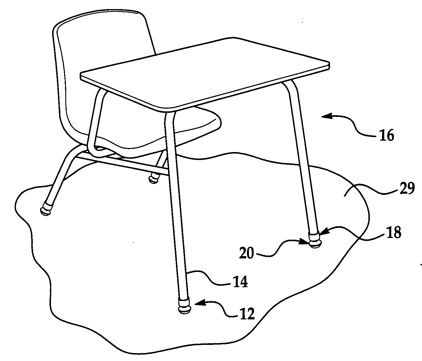
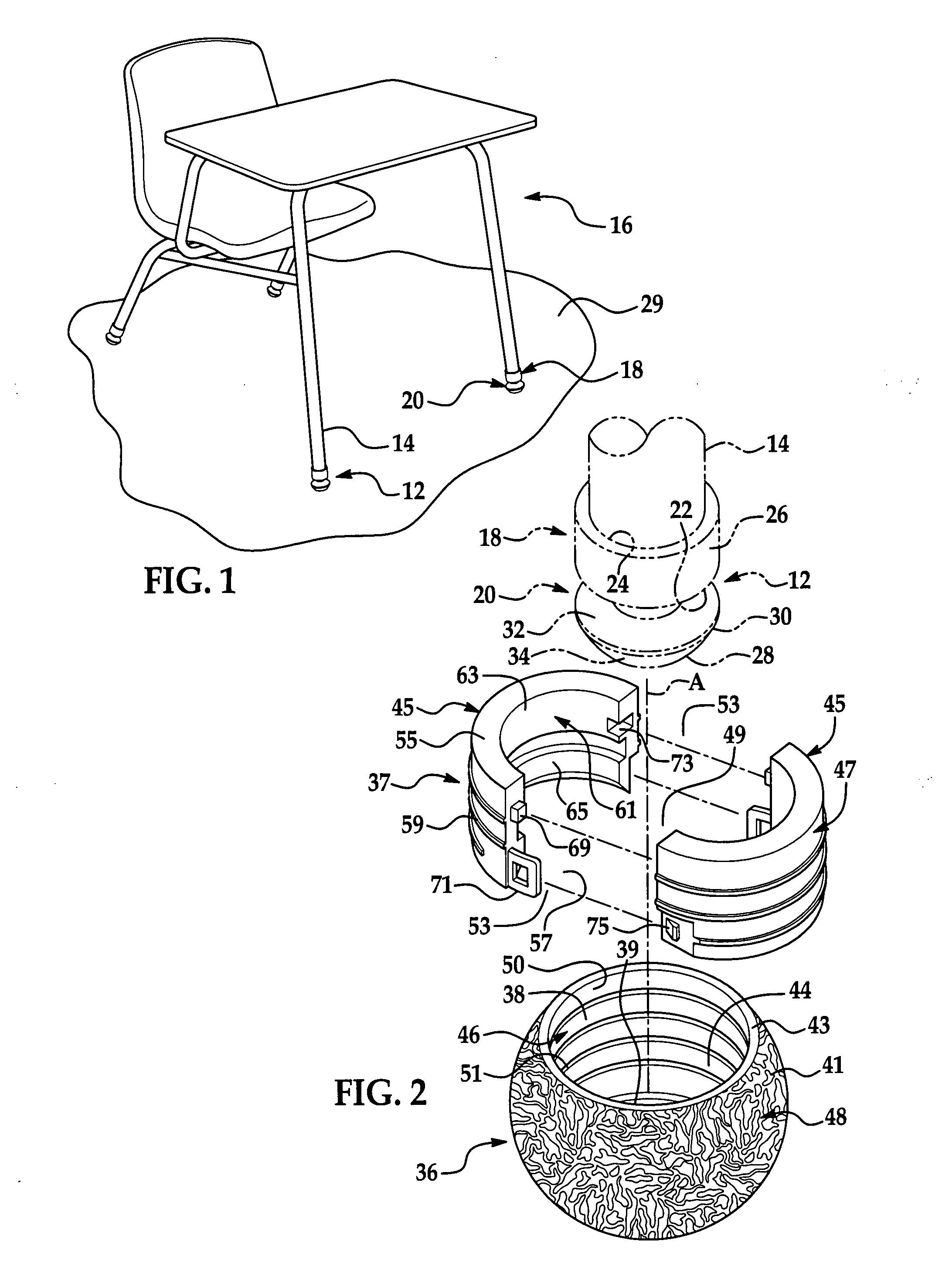
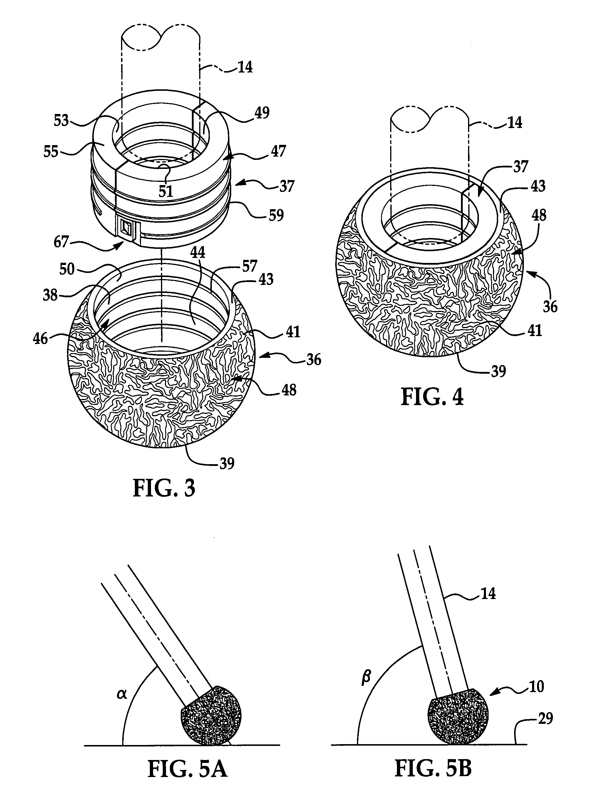
[0047]Referring now to the figures, where like numerals are used to designate like structure, three embodiments of a furniture-glide assembly of the present invention are generally indicated at 10, 110, 210. The glide assembly 10, 110, 210 is adapted to be mounted about an existing foot, generally indicated at 12 in FIGS. 1, 2, 9, and 13, that is attached to the free end of a leg 14 of a piece of furniture.

[0048]The foot 12 is described below and shown in the figures specifically attached about the free end of the leg 14. Also, the glide assembly 10, 110, 210 is described below and shown used in connection with a chair-desk combination, generally indicated at 16 in FIG. 1. However, it should be appreciated by those having ordinary skill in the related art that the glide assembly 10, 110, 210 can be used in connection with a chair and a desk that are not combined with each other and are, thus, free-standing. It should also be so appreciated that the foot 12 and, thus, glide assembly ...


PUM


Abstract

A glide assembly is adapted to be mounted about an existing foot attached to the free end of a leg of a piece of furniture. The glide assembly includes a body defining an exterior surface and a bore extending partially through the body to define a hollow interior, an interior surface, and an open end of the body. An insert assembly is removably mountable about the foot and adapted to be received through the open end and fixedly secured within the hollow interior of the body so as to mount the body about the foot.

Description

BACKGROUND OF THE INVENTION[0001]1. Field of the Invention[0002]The present invention relates, in general, to a glide attachable to a leg of a piece of furniture and, in particular, to a glide assembly mountable about an existing foot attached to the free end of a leg of a chair or desk.[0003]2. Description of the Related Art[0004]The free end of each leg of a piece of furniture often includes a cap, foot, glide, or the like. In many institutionalized settings, such as in a school or other educational facility, the feet disposed on the free end of the legs of a piece of furniture are designed to allow easy sliding of a chair or desk, for instance, upon a surface such as a floor. More specifically, the feet are designed to increase the amount of surface-area contact, but reduce the amount of frictional contact, between the legs and the floor.[0005]One type of foot commonly employed in the related art generally includes an attachment portion and a gliding portion. The attachment porti...

Claims


Application Information

Patent Timeline
IPC IPC(8): A47B91/00
CPCA47B91/06A47B91/12Y10T16/209Y10T16/21A47C7/002
Inventor CHASE, JOHN
Owner HIWATT PROD
Features
  • Generate Ideas
  • Intellectual Property
  • Life Sciences
  • Materials
  • Tech Scout
  • Unparalleled Data Quality
  • Higher Quality Content
  • 60% Fewer Hallucinations
Learn More