Arrangement for failsafe evaluation of a position encoder

Active Publication Date: 2008-10-09
PILZ (COMPANY)
View PDF1 Cites 9 Cited by
  • Summary
  • Abstract
  • Description
  • Claims
  • Application Information

AI Technical Summary

Benefits of technology

[0014]In contrast, in all hitherto known approaches for evaluating and monitoring an impedance-based position encoder, only a divider ratio of the partial impedances is measured. Although it is possible, if the total impedance is known, to calculate the partial impedances, they are not measured separately from each other. The new procedure makes it possible to compare the partial impedances, which are determined separately from one another, with each other and / or with the known or measured total impedance. This enables a plurality of plausibility checks which are very easy to implement in circuitry, and also extremely straightforward, redundant evaluation. In a particularly preferred exemplary embodiment, the new arrangement requires just one fixed resistor in addition to two microcontrollers, for example. Two microcontrollers are frequently used anyway in safety switching devices for reasons of redundancy, so that the component cost here is extremely low.
[0039]The use of integrated circuits is particularly advantageous to implement the first evaluation circuit and second evaluation circuit using a microcontroller, microprocessor, FPGA or other integrated logic circuits. The number of components required is thereby minimized. The manufacturing costs and overall space required are correspondingly low.

Problems solved by technology

They are not designed to be “failsafe”, however, and hence cannot ensure the desired level of personnel protection.
For reasons of failsafety, however, at least two redundant position encoders are used for safety switching devices, which is a disadvantage because of the component costs and the need of assembly.
This restricts the minimum overall size of a safety switching device.
The disadvantage with this method is that the voltage range that can be varied by means of the potentiometer is reduced by the fixed resistors connected in series.
In addition, measurement of the potentiometer position is subject to inaccuracies dependent on the tolerances of the fixed resistors.
Finally, this circuit is expensive if a plurality of potentiometers are to be evaluated with failsafe reliability.
These solutions are also expensive, in particular if a plurality of potentiometers are to be monitored with failsafe reliability.
In addition, the number of potentiometer positions that can be distinguished from each other is again limited because of tolerances of additional components.

Method used


Image

  • Arrangement for failsafe evaluation of a position encoder
  • Arrangement for failsafe evaluation of a position encoder
  • Arrangement for failsafe evaluation of a position encoder

Examples


Embodiment Construction

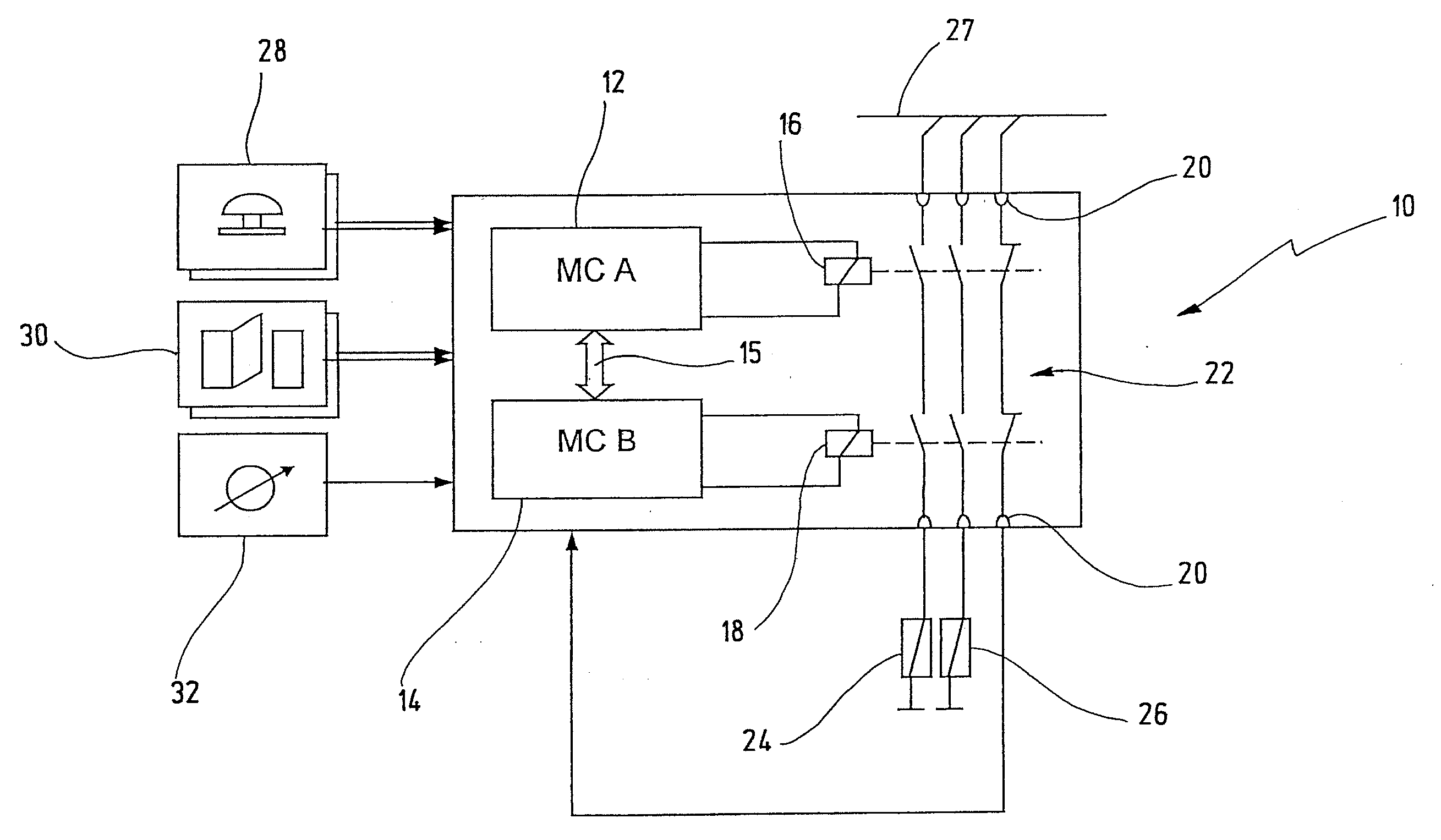
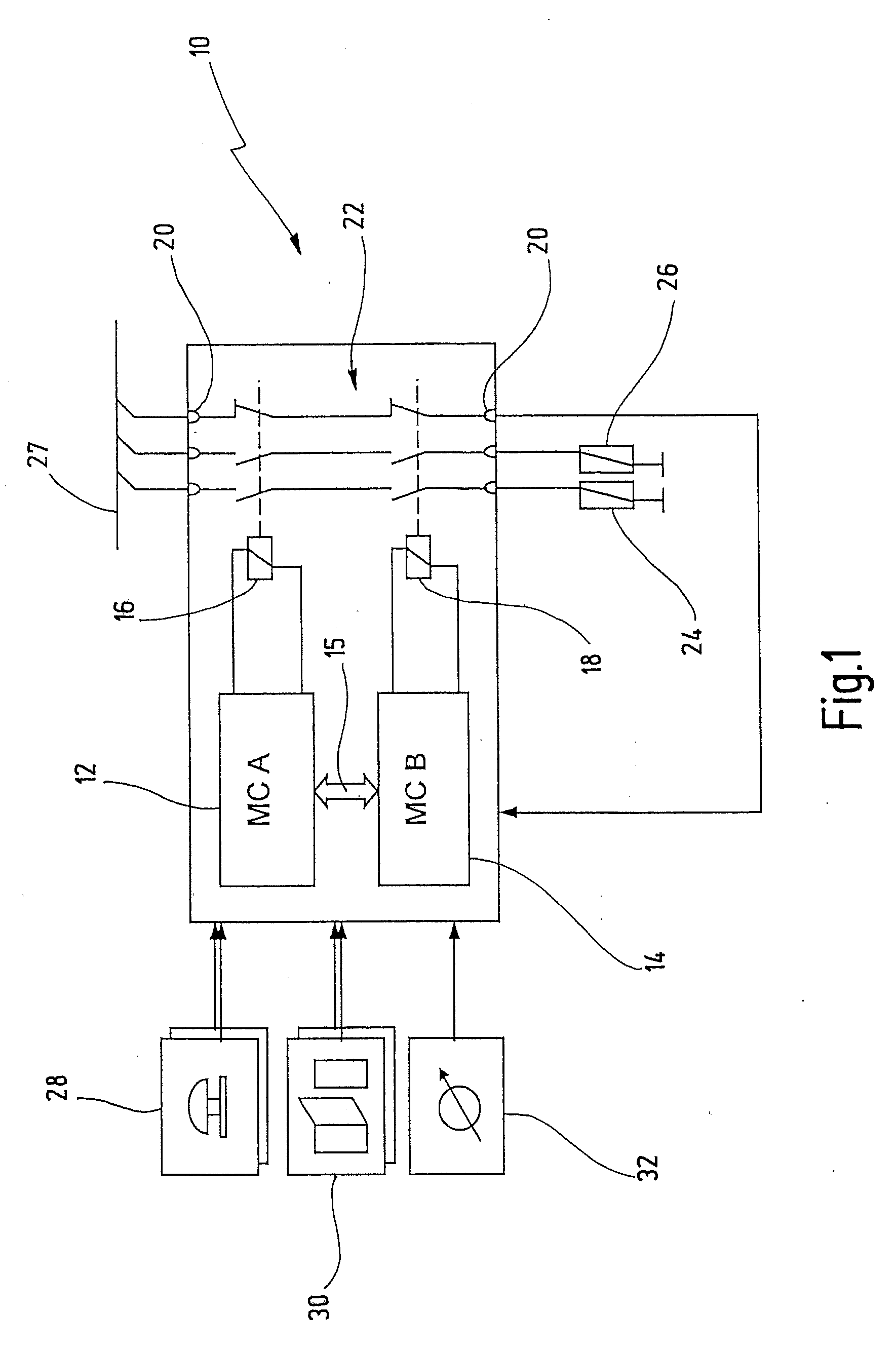
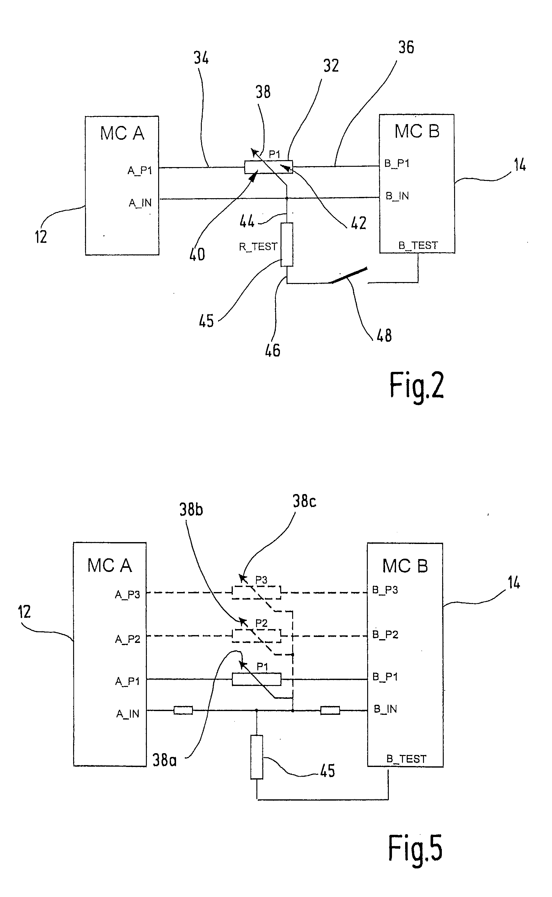
[0049]In FIG. 1, a safety switching device is denoted in its entirety by reference number 10. The safety switching device 10 has a dual-channel design and has two microcontrollers 12, 14, which can communicate with each other via a link 15 in order to compare their data and monitor each other. The link 14 may be a dual-port RAM or a communications interface (e.g. UART) for example.

[0050]Each of the microcontrollers 12, 14 controls a relay 16, 18. The switching contacts of the relays 16, 18 lie in series with each other between connecting terminals 20 of the safety switching device 10. They thus form current paths 22 between the connecting terminals 20, which can be opened with failsafe reliability by the microcontrollers 12, 14. The normally-open contacts of the relays 16, 18 form two current paths 22, via which two contractors 24, 26 are connected to an external power supply 27. The contractors 24, 26 are electrical loads in the sense of the present invention and are used, for exam...


PUM


Abstract

A safety switching device comprises a position encoder, such as a potentiometer, for user selection of an operational quantity, such as an operating mode. The position encoder has a first terminal, a second terminal, and a tap moveable through a plurality of positions. A total impedance is defined between the first terminal and the second terminal. A first partial impedance is defined between the first terminal and the tap, and a second partial impedance is defined between the tap and the second terminal. An arrangement for determining an instantaneous position of the tap comprises a first evaluation circuit designed to determine a first measurement value representative of the first partial impedance, and a second evaluation circuit designed to determine a second measurement value representative of the second partial impedance. At least one from the first and second evaluation circuits is designed to determine the instantaneous position of the tap by means of the first and second measurement values.

Description

CROSS-REFERENCES TO RELATED APPLICATIONS[0001]This application is a continuation of international patent application PCT / EP2006 / 008149, filed on Aug. 18, 2006 designating the U.S., which international patent application has been published as WO 2007 / 039017 A1 in German language and claims priority from German patent application DE 10 2005 048 601.0, filed on Oct. 6, 2005. The entire contents of these priority applications are incorporated herein by reference.BACKGROUND OF THE INVENTION[0002]The present invention relates to a safety switching device for failsafe disconnection of an electrical load, such as a drive of a dangerous machine, and to an arrangement for failsafe evaluation of a position encoder provided for user selection of an operational quantity, such as an operating mode, in such a safety switching device. More particularly, the invention relates to an arrangement for failsafe evaluation of a position encoder having a first terminal, a second terminal and a moveable tap...

Claims


Application Information

Patent Timeline
IPC IPC(8): H02H1/00
CPCG01D3/08G01R27/08G01R31/2829H01H47/004
Inventor PULLMANN, JUERGENNITSCHE, THOMASHORNUNG, GUENTERZINSER, CHRISTOPH
Owner PILZ (COMPANY)
Why Eureka
Try Eureka